

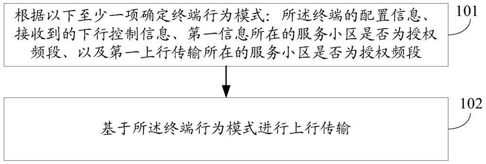
Uplink transmission method and terminal
A transmission method and terminal technology, applied in the field of communication, can solve the problems of low uplink transmission efficiency of terminals, achieve the effects of increasing uplink transmission opportunities, improving throughput and delay, and improving efficiency
- Summary
- Abstract
- Description
- Claims
- Application Information
AI Technical Summary
Problems solved by technology
Method used
Image

Examples
example 1
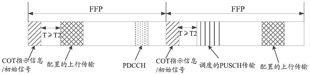
[0061] In this example 1, the network system uses FBE, and for the UE in the connected state (CONNECTED), the UE configures the corresponding FFP, and configures the UE to detect at least one of the COT indication information, the initial signal and the preamble signal in each FFP . If the UE detects at least one of the COT indication information, the initial signal and the preamble signal, the UE may perform uplink transmission or downlink reception according to the indication content of at least one of the COT indication information, the initial signal and the preamble signal. If in a certain FFP, the UE does not detect at least one of the COT indication information, the initial signal and the preamble signal, and the UE has configured uplink transmission in the FFP, the UE may cancel the transmission of the configured uplink transmission.
[0062] If the UE supports cross-FFP scheduling, such as figure 2 As shown, the UE receives PDCCH in the first FFP, which schedules th...
example 2
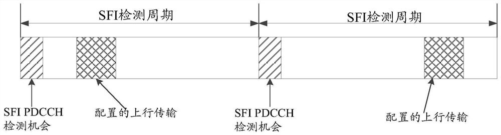
[0065] In this example 2, the network system uses FBE. For the UE in the connected state (CONNECTED), the UE is configured to detect SFI PDCCH, and the UE does not have a semi-static slot format configuration, that is, there is no tdd-UL-DL-ConfigurationCommon and / or tdd -UL-DL-ConfigurationDedicated; or, the UE is configured to detect SFI PDCCH, and the configured uplink transmission is configured on the flexible symbol configured in the semi-static slot format. Such as image 3As shown, if the UE does not detect the SFI PDCCH at the SFI PDCCH detection opportunity in a certain SFI detection period, the UE can perform idle channel detection before transmitting the configured uplink transmission; if the channel is detected to be idle, the UE transmits the SFI PDCCH configured uplink transmission; or, if the channel is detected to be busy, the UE does not transmit the configured uplink transmission.
example 3
[0067] When the UE is configured with CA (Carrier Aggregation, carrier aggregation), the UE can receive or transmit on multiple component carriers, and the UE needs to know which component carrier the DCI corresponds to. This information can be implicit or explicit, depending on whether cross-carrier scheduling is used, and cross-carrier scheduling is implemented independently for each component carrier of each UE through RRC signaling. Whether to use cross-carrier scheduling is configured by high-layer signaling.
[0068] For non-cross-carrier scheduling, each component carrier is configured with a PDCCH, and the downlink scheduling information on the component carrier is all for this component carrier. For uplink authorization, there is an association between uplink and downlink component carriers, and each uplink component carrier corresponds to an associated downlink component carrier, and this association information is part of the system information. Therefore, from the...
PUM
 Abstract
Description
Claims
Application Information