
Dehumidification mechanism of hardware storage cabinet and working method thereof

A storage cabinet and hardware storage technology, which is applied to the cleaning method of tools, metal processing equipment, cleaning methods and utensils, etc., can solve the problems of labor-intensive, low cleaning efficiency, incomplete cleaning, etc., and achieves reduction of manual turnover and dehumidification. Thoroughly improve the effect of dehumidification

Inactive Publication Date: 2021-03-30
马鞍山天哲环保科技有限公司
View PDF12 Cites 0 Cited by
  • Summary
  • Abstract
  • Description
  • Claims
  • Application Information

AI Technical Summary

Problems solved by technology

[0004] The purpose of the present invention is to provide a dehumidification mechanism and working method of a hardware storage cabinet, which solves the problem of cleaning up the residue and moisture on the surface of the storage cabinet by manual wiping. , when dehumidifying, through manual wiping, during the wiping process, continuous operation is not possible, and omissions are likely to occur, and the technical problems of incomplete cleaning

Method used


Image

  • Dehumidification mechanism of hardware storage cabinet and working method thereof
  • Dehumidification mechanism of hardware storage cabinet and working method thereof
  • Dehumidification mechanism of hardware storage cabinet and working method thereof

Examples


Embodiment approach

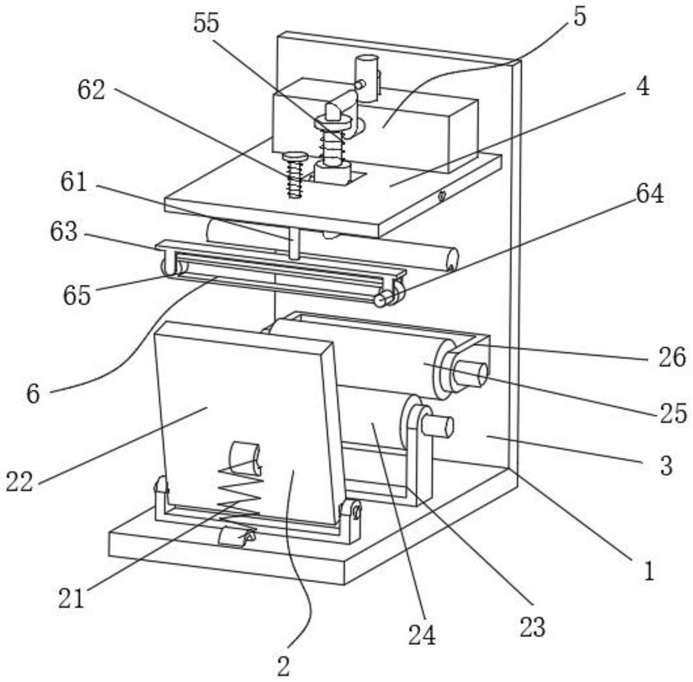
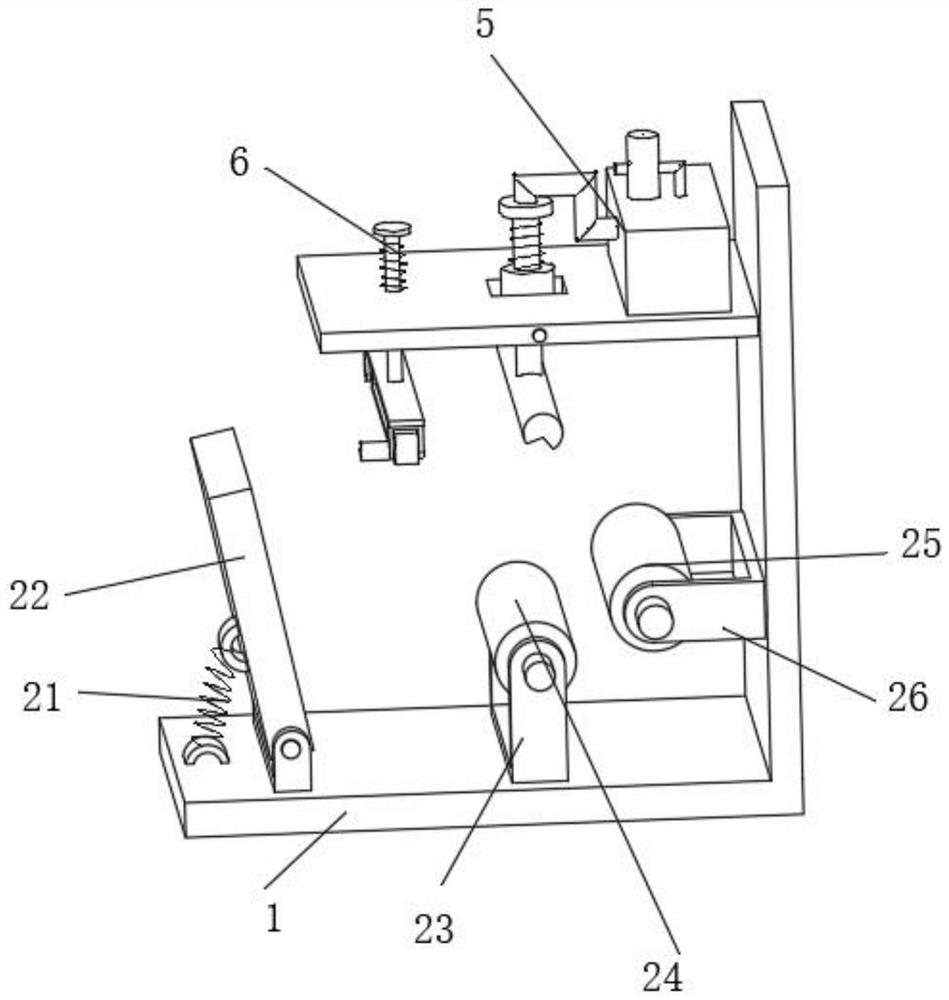
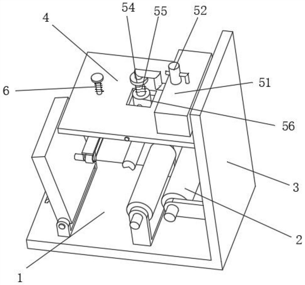
[0030] As an embodiment of the present invention, the clamping and turning structure 2 includes a clamping spring 21, a clamping plate 22, a first roller frame 23, a first rubber roller 24, a second rubber roller 25, and a second roller frame 26. The holding plate 22 is mounted on the top side of the base 1 through a hinge, the bottom side of the clamping plate 22 and the top side of the base 1 are fixed with a clamping spring 21 at an oblique angle, and the first roller frame 23 is welded on the On the top side of the base 1, the first rubber roller 24 is installed inside the first roller frame 23 through the roller shaft fit, the second roller frame 26 is welded on one side of the fixed plate 3, and the second rubber roller 25 is fitted through the roller shaft Installed on the second roll frame 26, the first roll frame 23 and the second roll frame 26 are arranged at right angles, and the clamping plate 22 is arranged in parallel with the first rubber roller 24. During work, ...


PUM


Abstract

The invention discloses a dehumidification mechanism of a hardware storage cabinet and a working method thereof. The dehumidification mechanism comprises a base, a clamping turnover structure, a fixing plate, a supporting frame, a dehumidification structure and a grinding structure, the dehumidification structure is installed in the middle of the supporting frame, and the grinding structure is installed at the end of the supporting frame. According to the clamping turnover structure, under the cooperation of clamping springs and the rotation cooperation of a first rubber roller and a second rubber roller, clamping plates can achieve overturning of the storage cabinet, continuous overturning can be achieved, manual overturning is reduced, the dehumidification effect is improved, the dehumidification structure is mounted, under cooperation of a shrinkage spring, pushing of a telescopic pipe can be achieved, during pushing, a suction nozzle can be better attached to the surface of a storage box for cleaning, under the cooperative operation of an emptying pump, emptying of a dust collection box can be achieved, cleaning of the storage cabinet can be achieved, cleaning and removing canbe conducted along the surface of the storage cabinet, the surface of the storage cabinet can be completely cleaned, and dehumidification is more thorough.

Description

technical field [0001] The invention relates to the technical field of dehumidification of storage cabinets, in particular to a dehumidification mechanism of a hardware storage cabinet and a working method thereof. Background technique [0002] The storage cabinet is generally used for the storage and storage of various items. During the long-term use of the storage cabinet, it is easily eroded by the external environment. The surface of the storage cabinet is wet, which will rust and reduce the service life. [0003] In the dehumidification treatment of the storage cabinet, the residue and moisture on the surface of the storage cabinet are generally cleaned by manual wiping. The cleaning process is complicated, labor-intensive, inconvenient to turn the storage cabinet, and the cleaning efficiency is low. , can not operate continuously, prone to omissions, incomplete cleaning, when dehumidifying the storage cabinet, after the storage cabinet is corroded, it is not possible t...

Claims


Application Information

Patent Timeline
Patent Type & Authority Applications(China)
IPC IPC(8): B08B1/02B24B19/00B24B41/06B24B47/12B24B55/06
CPCB24B19/00B24B41/06B24B47/12B24B55/06B08B1/20
Inventor 游登洲沈玉鹏刘宪文刘成
Owner 马鞍山天哲环保科技有限公司
Learn More