Teacup filter side edge perforating device

A filter and teacup technology, which is applied in the direction of feeding device, positioning device, storage device, etc., can solve the problems of inconvenient operation of the filter, complex structure, etc.

Pending Publication Date: 2021-03-30
邓利成
View PDF7 Cites 0 Cited by
  • Summary
  • Abstract
  • Description
  • Claims
  • Application Information

AI Technical Summary

Problems solved by technology

[0005] In order to overcome the disadvantages of complex structure, inconvenient operation and the need to manually place the filter in the prior art, the purpose of the present invention is to provide a teacup filter side hole opening device that is easy to operate and can automatically unload the filter

Method used


Image

  • Teacup filter side edge perforating device
  • Teacup filter side edge perforating device
  • Teacup filter side edge perforating device

Examples


Embodiment 1

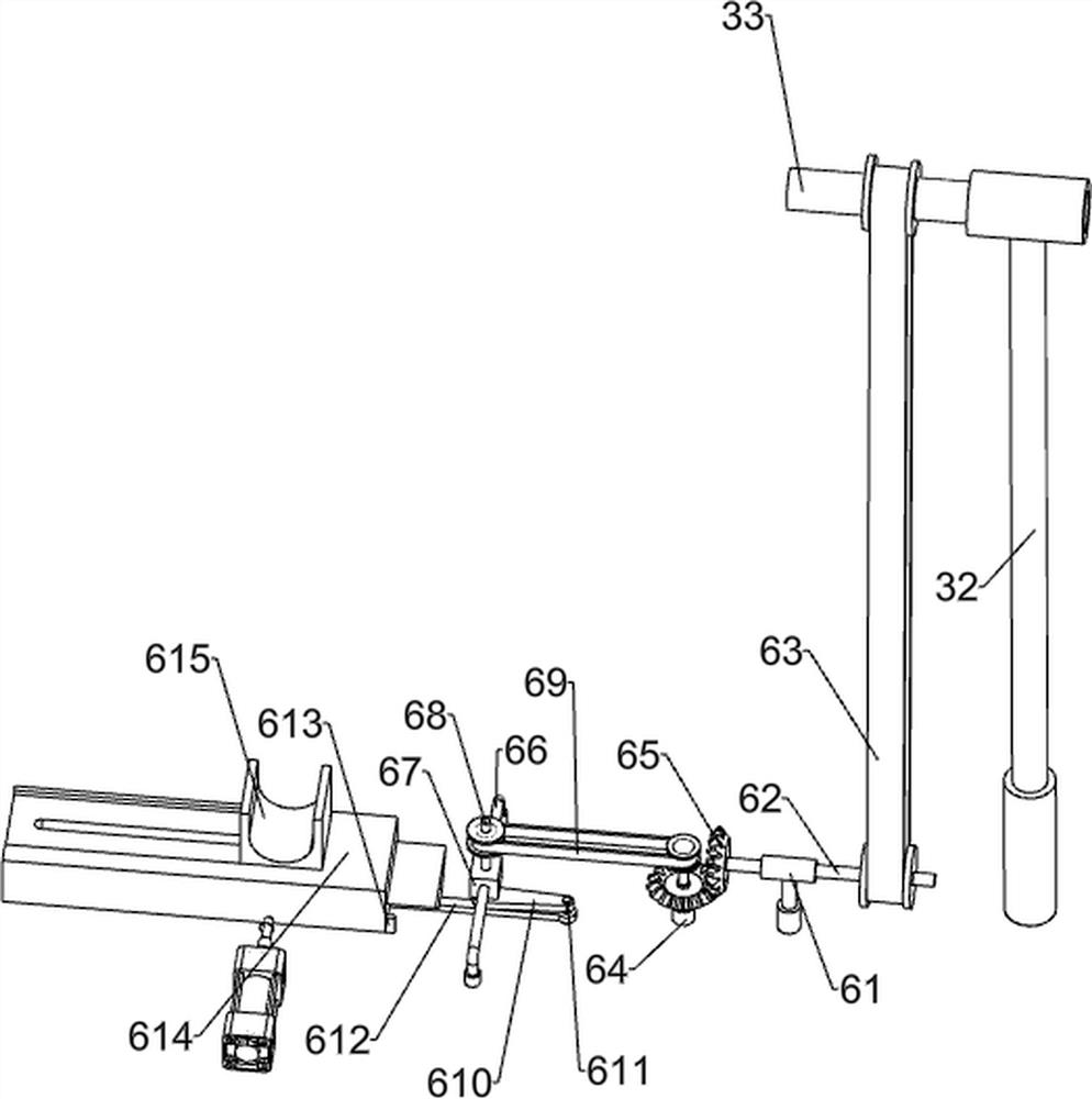
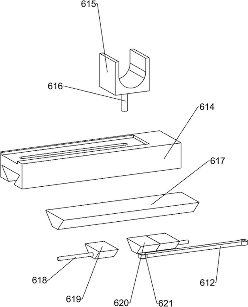
[0031] A device for opening holes on the side of a teacup filter, such as Figure 1-8 and Figure 11 As shown, it includes a bottom plate 1, a workbench 2, a transmission mechanism 3, a punching mechanism 4, an intermittent rotation mechanism 5, a feeding mechanism 6, a material pushing mechanism 7 and a servo motor 8. There are workbenches on both sides of the top of the bottom plate 1. 2. A transmission mechanism 3 is provided between the workbench 2 on the rear side and the bottom plate 1, a punching mechanism 4 is provided on the workbench 2 on the rear side, an intermittent rotation mechanism 5 is provided on the workbench 2 on the rear side, and the workbench 2 A feeding mechanism 6 is arranged between them, a pushing mechanism 7 is arranged on the workbench 2 on the front side, and a servo motor 8 is arranged on the transmission mechanism 3 .

[0032] When people need to use this device, first people start the servo motor 8 to rotate forward, the output shaft of the se...

Embodiment 2

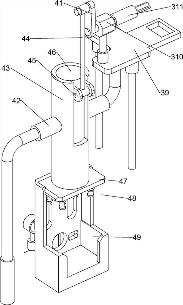
[0044] On the basis of Example 1, such as Figure 9-11 As shown, it also includes a top column 9, an L-shaped block 10, a second clamping block 11, a clamping plate 12, a slide rail 13, a guide rod 14, a fourth elastic member 15, a fifth elastic member 16 and an extrusion plate 17, The front side of the circular gear 511 is provided with a top post 9, the lower right part of the rear side of the fixed frame 49 is provided with an L-shaped block 10, and the L-shaped block 10 is rotatably provided with a second block 11, which cooperates with the top post 9 , the inner walls of the left and right sides of the fixed frame 49 are provided with slide rails 13, the left and right sides of the fixed frame 49 are provided with guide rods 14, and the guide rods 14 are equipped with a fourth elastic member 15, and the fourth elastic member 15 is Tension spring, the fifth elastic member 16 is arranged between the L-shaped block 10 and the second clamping block 11, and the fifth elastic m...


PUM


Abstract

The invention relates to a perforating device, in particular to a teacup filter side edge perforating device. The teacup filter side edge perforating device is easy to operate and capable of automatically discharging a filter. The teacup filter side edge perforating device comprises a bottom plate, a transmission mechanism, a punching mechanism, an intermittent rotating mechanism, a feeding mechanism and a pushing mechanism, and a plurality of workbenches are arranged at the top of the bottom plate. The transmission mechanism is arranged between the workbenches on one side and the bottom plate. The punching mechanism is arranged on the workbenches on one side. The intermittent rotating mechanism is arranged on the workbenches on one side. The feeding mechanism is arranged between the workbenches. The pushing mechanism is arranged on the workbenches on the other side. According to the teacup filter side edge perforating device, the punching action on a filter is achieved through the punching mechanism, then, under cooperation of the transmission mechanism, the intermittent rotating mechanism, the feeding mechanism and the pushing mechanism, punching on the filter can be efficientlyand stably achieved, and the intermittent rotating mechanism can drive the filter to intermittently rotate.

Description

technical field [0001] The invention relates to a device for opening holes, in particular to a device for opening holes on the side of a teacup filter. Background technique [0002] Drinking tea is not only a traditional food culture, but at the same time, because tea contains a variety of antioxidant substances and antioxidant nutrients, it has a certain effect on eliminating free radicals, so it has an anti-aging effect. [0003] Moreover, tea contains a variety of vitamins and amino acids. Drinking tea also has a certain effect on clearing oil and degreasing, enhancing nerve excitement, digestion and diuresis, so it has the function of health care. Therefore, tea drinking culture is a traditional culture in China, which has always been loved by people. A teacup is essential as a utensil for making tea. A general teacup includes a cup body and a filter stuck in the middle of the cup body. Before the filter is sold, people usually need to punch it. At present, the existin...

Claims


Application Information

Patent Timeline
IPC IPC(8): B21D31/02B21D43/02B21D43/04B21D43/13B21D43/14B21D45/02B30B1/26
CPCB21D31/02B21D43/026B21D43/04B21D43/13B21D43/14B21D45/02B30B1/26
Inventor 邓利成
Owner 邓利成
Why Eureka
Try Eureka