
Filtering information configuration method and system

A technology for filtering information and configuring methods, applied in the field of communication, can solve problems such as the impact of key service quality, and achieve the effect of improving processing quality

Active Publication Date: 2021-03-30
ZTE CORP
View PDF6 Cites 0 Cited by
  • Summary
  • Abstract
  • Description
  • Claims
  • Application Information

AI Technical Summary

Problems solved by technology

[0005] The embodiment of the present disclosure provides a filter information configuration method, device and system, to at least solve the problem that the quality of key services is greatly affected by the delayed reporting of fault events in related technologies problem of influence

Method used


Image

  • Filtering information configuration method and system
  • Filtering information configuration method and system
  • Filtering information configuration method and system

Examples


Embodiment 1

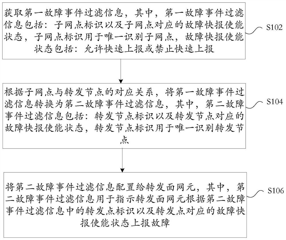
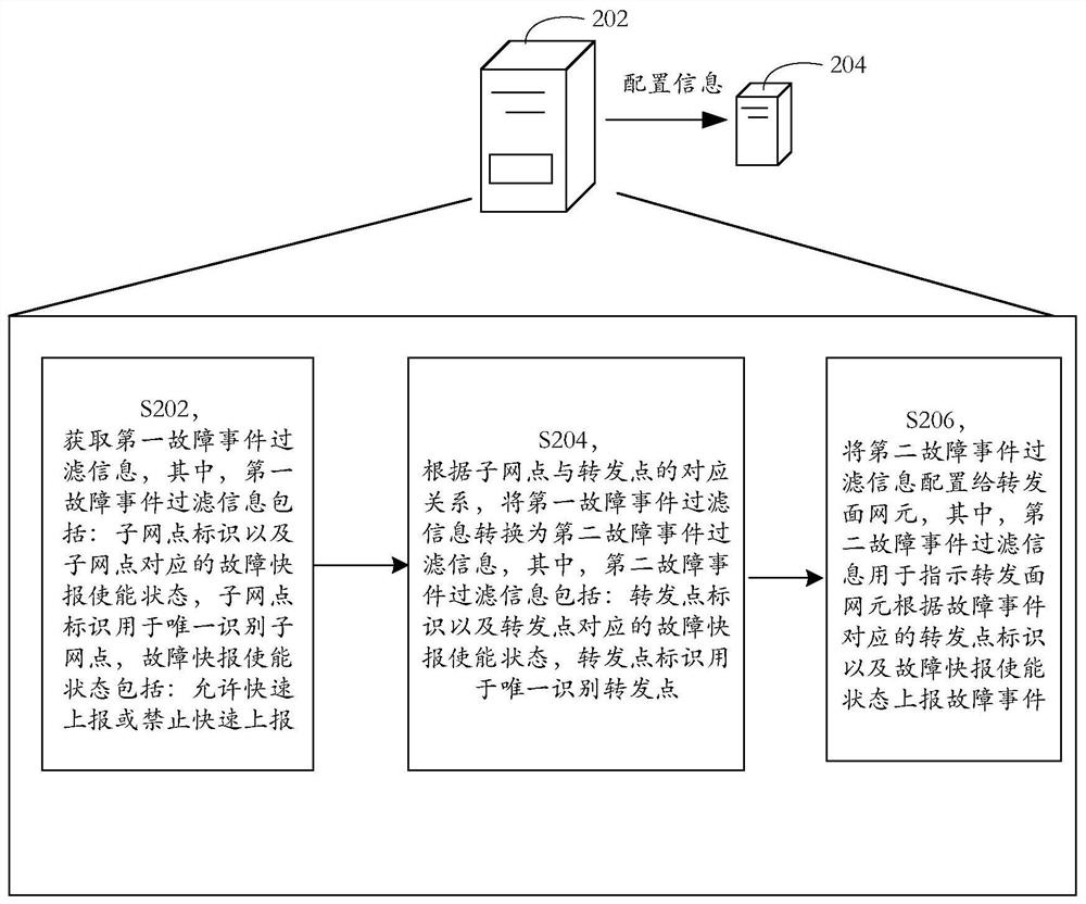
[0028] The embodiment of the present disclosure provides a filtering information configuration method. figure 1 is a flowchart of an optional filtering information configuration method in the embodiment of the present disclosure, such as figure 1 As shown, the method includes:

[0029] Step S102, obtain the first fault event filtering information, wherein, the first fault event filtering information includes: sub-network point identifier and fault express enabling status corresponding to the sub-network point, the sub-network point identifier is used to uniquely identify the sub-network point, fault express enabling status Including: allow rapid reporting or prohibit rapid reporting;

[0030] Step S104, according to the corresponding relationship between the sub-network point and the forwarding point, the first fault event filtering information is converted into the second fault event filtering information, wherein the second fault event filtering information includes: the fo...

Embodiment 2

[0120] In order to better understand the technical solutions provided by the embodiments of the present disclosure, specific examples are used below to illustrate.

example 1

[0122] Figure 9 is an optional forwarding plane network element topology diagram according to an embodiment of the present disclosure, such as Figure 9 As shown, in the topology composed of four forwarding plane network elements of ABCZ, they are interconnected through the optical transport unit OTU2 link. On this network, the optical data unit ODU1 connection between the 8# port of point A and the 8# port of point Z can be established through the MCC system, such as the SDN controller or the control plane. Figure 6Fault monitoring related to tandem connection monitor (Tandem Connection Monitor, TCM for short) is not configured in the shown topology. The forwarding plane resource used by the connection, that is, the binding relationship between the Subnetwork Point (SNP for short) and the FP / FwEP is shown in Table 1.

[0123] Table 1

[0124] SNP identification Bound FP resources SNP-A8 1#ODU1 of port 8#OTU2 of NE A SNP-A1 1#ODU1 of port 1#OTU2 ...


PUM


Abstract

The embodiment of the invention provides a filtering information configuration method and system. The method comprises the steps that first fault event filtering information is acquired; the first fault event filtering information is converted into second fault event filtering information according to the corresponding relation between the sub-network points and the forwarding points, the second fault event filtering information comprises forwarding point identifiers and fault fast message enabling states corresponding to the forwarding points, and the forwarding point identifiers are used foruniquely identifying the forwarding points; and the second fault event filtering information is configured to the forwarding plane network element, the second fault event filtering information beingused for indicating the forwarding plane network element to report a fault according to a forwarding point identifier in the second fault event filtering information and a fault fast report enabling state corresponding to the forwarding point. The problem that the quality of key services is greatly influenced due to delayed reporting of fault events in the prior art is solved.

Description

technical field [0001] The present disclosure relates to the technical field of communications, and in particular, to a filtering information configuration method and system. Background technique [0002] The Management Control Continuum (MCC) system integrates essentially the same management functions and control functions together to realize unified management and control of transmission resources and provide integrated management and control services for upper-layer users. [0003] The MCC system connects to the network elements on the forwarding plane. When the resources on the forwarding plane fail and the connection is affected, the MCC system needs to start the connection recovery. In traditional network elements, faults generally need to be confirmed before they are reported to the management plane or network management system of the MCC system. The time to confirm that a fault occurs is 2±0.5 seconds, and the time to confirm that a fault disappears is 10±0.5 seconds...

Claims


Application Information

Patent Timeline
IPC IPC(8): H04L12/24
CPCH04L41/0604H04L41/0823H04L41/0895
Inventor 牛小兵
Owner ZTE CORP
Learn More