Bird repelling device for power equipment
A kind of power equipment and bird repelling technology, applied in the direction of cable installation, application, electrical components, etc., can solve the problem of roosting birds
- Summary
- Abstract
- Description
- Claims
- Application Information
AI Technical Summary
Problems solved by technology
Method used
Image
Examples
Embodiment 1
[0028] This embodiment is an embodiment of a bird repelling device for electric equipment.
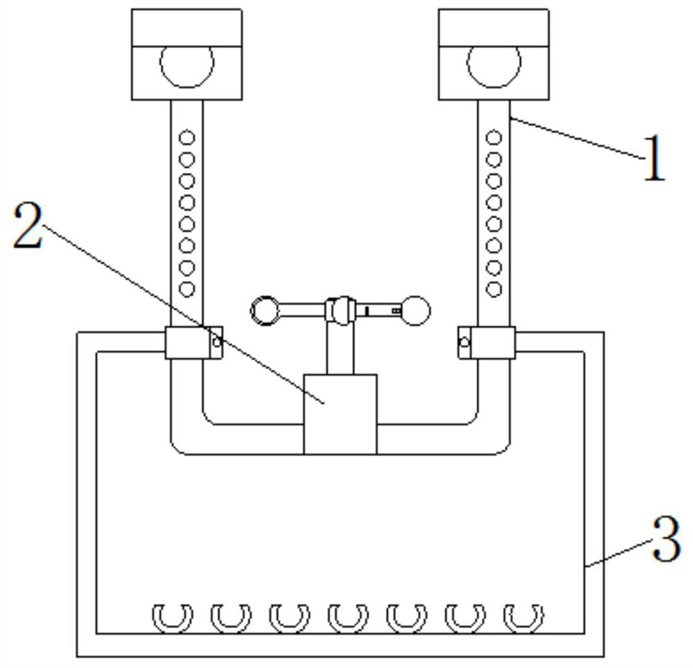
[0029] see Figure 1-3 , a bird repelling device for electric equipment, comprising a fixing mechanism 1, a bird repelling mechanism 2 and an auxiliary mechanism 3, the outer surface of the bottom of the fixing mechanism 1 is fixedly connected with the bird repelling mechanism 2, and the outer surface of the fixing mechanism 1 is fixedly connected with auxiliary body 3;
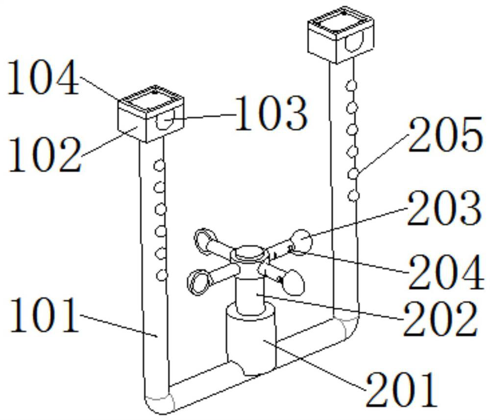
[0030] The fixing mechanism 1 includes a fixed frame 101, the top of the fixed frame 101 is fixedly connected with a connecting block 102, and the connecting block 102 is used to increase the connection area, thereby making the fixing more reliable, and the connecting block 102 is an insulating material, and the connecting block 102 The top of 102 is provided with a connection groove 103, the radian of the connection groove 103 is adapted to the size of the wire, the top bolt of the connection block 102 is connected ...
Embodiment 2
[0045] This embodiment is an embodiment of a bird repelling mechanism used in electric equipment.
[0046] A bird repelling mechanism 2 for power equipment, comprising a wind motor 201 and an LED flashing light 205 fixedly connected to the surface of the fixed frame 101, the upper end of the wind motor 201 is provided with a connecting transmission shaft 202, and the outer surface of the connecting transmission shaft 202 is fixed A wind pendulum 203 is connected, and the outer surface of the wind pendulum 203 is provided with a whistle groove 204;
[0047] Through the above technical scheme, the fixed frame 101 is set and the wind motor 201 is set on the fixed frame 101, and the wind pendulum 203 is set on the connecting transmission shaft 202 of the wind power motor 201 and the whistle groove 204 is set on the pole of the wind pendulum 203, The wind blows the wind pendulum 203 to rotate to make the wind motor 201 generate electricity and store energy so that the LED flashing li...
Embodiment 3
[0049] This embodiment is an embodiment of an auxiliary mechanism for electric equipment.
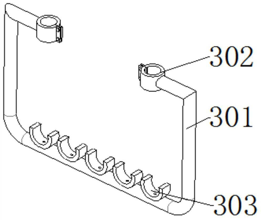
[0050] An auxiliary mechanism 3 for electric equipment includes a support frame 301 , a connecting hoop 302 is fixedly connected to the opposite end of the top of the support frame 301 , and an auxiliary support 303 is fixedly connected to the outer surface of the bottom of the support frame 301 .
[0051] Through the above technical scheme, the support frame 301 fixed on the fixed frame 101 is set, and the auxiliary bracket 303 is fixedly connected to the outer surface of the support frame 301, so that the electrician can hang the safety rope when performing line maintenance, and when erecting the auxiliary line There is no need to add additional steel strands, and spraying warning colors on the outside of the support frame 301 can play a warning role, achieving a multi-functional effect.
PUM
 Abstract
Description
Claims
Application Information
 - R&D
- Intellectual Property
- Life Sciences
- Materials
- Tech Scout
- Unparalleled Data Quality
- Higher Quality Content
- 60% Fewer Hallucinations
Browse by: Latest US Patents, China's latest patents, Technical Efficacy Thesaurus, Application Domain, Technology Topic, Popular Technical Reports.
© 2025 PatSnap. All rights reserved.Legal|Privacy policy|Modern Slavery Act Transparency Statement|Sitemap|About US| Contact US: help@patsnap.com


