Backlight module and display device

A backlight module and backplane technology, applied in optics, nonlinear optics, instruments, etc., can solve problems such as shadows or dark areas, achieve the effect of improving shadow problems and enhancing reflection effects

Pending Publication Date: 2021-04-02
WUHAN CHINA STAR OPTOELECTRONICS TECH CO LTD
View PDF0 Cites 7 Cited by
  • Summary
  • Abstract
  • Description
  • Claims
  • Application Information

AI Technical Summary

Problems solved by technology

[0004] The purpose of this application is to provide a backlight module and a display device to improve the problem of shadows or dark areas caused by splicing seams when lamp panels are spliced

Method used


Image

  • Backlight module and display device
  • Backlight module and display device
  • Backlight module and display device

Examples


no. 1 example

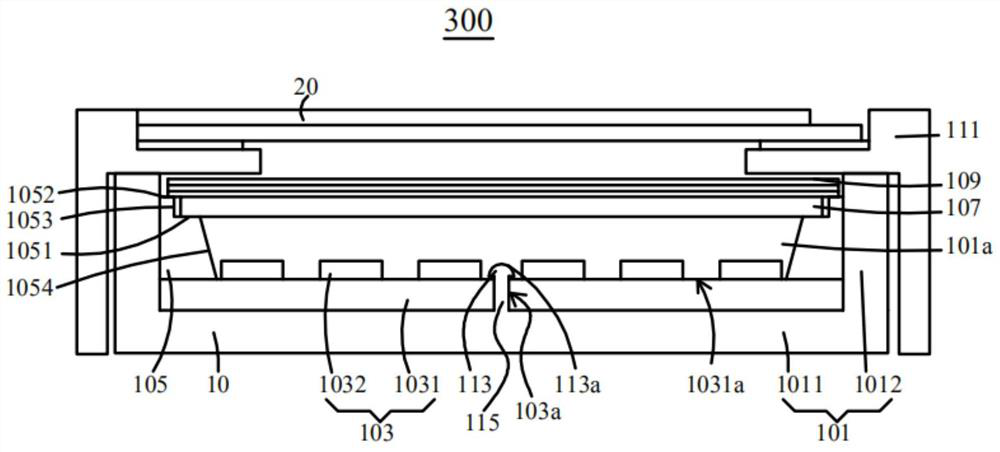
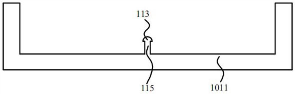
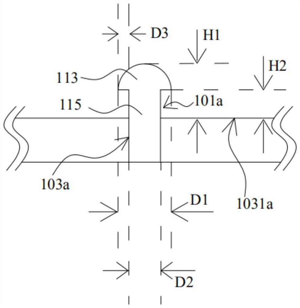
[0034] see Figure 1-Figure 3 , figure 1 is a schematic cross-sectional view of the display device according to the first embodiment of the present application, figure 2 for figure 1 The schematic plan view of the reflector connected to the back panel shown, image 3 for figure 1 A partially enlarged schematic view of the display device shown. The display device 300 includes a backlight module 10 and a liquid crystal display panel 20 . The display device 300 can be applied to a vehicle display or a television, and the like. The liquid crystal display panel 20 is located on the light emitting side of the backlight module 10. The backlight module 10 is used to provide a backlight for the liquid crystal display panel 20. The liquid crystal display panel 20 receives the backlight and controls the transmittance of the backlight, thereby displaying images of different gray scales.

[0035] In this embodiment, the liquid crystal display panel 20 includes an array substrate, a ...

no. 2 example

[0051] Such as Figure 4 and Figure 5 as shown, Figure 4 is a schematic diagram of a display device according to the second embodiment of the present application, Figure 5 for Figure 4 The schematic plan view of the reflector connected to the inner rubber frame is shown. Figure 4 The display device shown with the figure 1 The display devices shown are basically similar, and reflectors 113 are correspondingly provided at the seams 103a of two adjacent lamp panels 103, and the reflectors 113 are located on the edges of two adjacent lamp panels 103 close to the seams 103a. The point is that the reflective member 113 is connected to the inner rubber frame 105 , and the reflective member 113 serves as a beam of the inner rubber frame 105 to cover the splicing seam 103 a between adjacent lamp panels 103 .

[0052] The display device in the embodiment of the present application is connected to the inner rubber frame through the reflective member, so that the reflective memb...


PUM


Abstract

The invention provides a backlight module and a display device. The backlight module comprises: a plurality of lamp panels which are spliced with one another; and light reflecting pieces which are arranged corresponding to the splicing seams of the two adjacent lamp panels. By arranging the light reflecting pieces at the splicing seam of every two adjacent lamp panels, the reflecting effect of light at the splicing seam is improved, and the shadow problem at the splicing seam is solved.

Description

technical field [0001] The present application relates to the field of display technology, in particular to a backlight module and a display device. Background technique [0002] At present, for large-sized sub-millimeter light-emitting diode (mini-LED) backlight modules in vehicles, the light boards of sub-millimeter light-emitting diode backlight modules usually use spliced ​​light boards, that is, multiple light boards are spliced ​​into a whole lamp. board as a backlight. Due to the limitation of the light path propagation path of the direct-type backlight, when the large-size sub-millimeter light-emitting diode backlight module adopts the panel design, the treatment of the seam generated by the splicing between two adjacent light panels is currently encountered. One problem is that due to the existence of the seam, the light of the direct-lit backlight at the splicing position is relatively dark, which appears as a dark shadow or dark area optically on the product, whi...

Claims


Application Information

Patent Timeline
IPC IPC(8): G02F1/13357G02F1/1333
CPCG02F1/133602G02F1/133605G02F1/133608G02F1/133606G02F1/133308G02F1/133603
Inventor 周政宋岁忙
Owner WUHAN CHINA STAR OPTOELECTRONICS TECH CO LTD
Why Eureka
Try Eureka