
Multifunctional power transmission line deicing device

A power transmission line, multi-functional technology, applied in the installation of cables, overhead installation, electrical components, etc., can solve the problems affecting the normal life of residents, heavy workload, manpower consumption, etc., to avoid rapid freezing again and improve deicing effect of effect

Active Publication Date: 2021-04-02
国网山东省电力公司泗水县供电公司 +2
View PDF12 Cites 0 Cited by
  • Summary
  • Abstract
  • Description
  • Claims
  • Application Information

AI Technical Summary

Problems solved by technology

[0003] In the winter of our country, there is a lot of rain and snow in the north, and ice often occurs on the transmission line. If it is not cleaned up in time, it is easy to form an ice layer, which will increase the weight of the transmission line, break the transmission line, cause the circuit to be interrupted, and affect the normal life of the residents. Life
[0004] According to the knowledge of the inventor, the existing methods of removing ice on the transmission line include: manual beating, which is very labor-intensive, labor-intensive, and inefficient; mechanical deicing equipment, most of which use movable hammers or deicing mills Such a deicing method will cause the power transmission line to swing from side to side when there is wind blowing. At this time, these movable hammers or deicing milling cutters can easily cause damage to the transmission line when they are running on the transmission line. , causing unnecessary losses
[0005] The inventor also understands that existing automatic deicing devices have problems such as poor deicing effect and single function. ; When deicing is carried out by means of heating or a combination of mechanical and heating methods, the water obtained after the ice is heated and melted adheres to the high-voltage line and cannot be completely removed, which will cause the high-voltage line in a low-temperature environment to freeze again quickly. Repeated deicing brings huge workload

Method used


Image

  • Multifunctional power transmission line deicing device
  • Multifunctional power transmission line deicing device
  • Multifunctional power transmission line deicing device

Examples


Embodiment 1

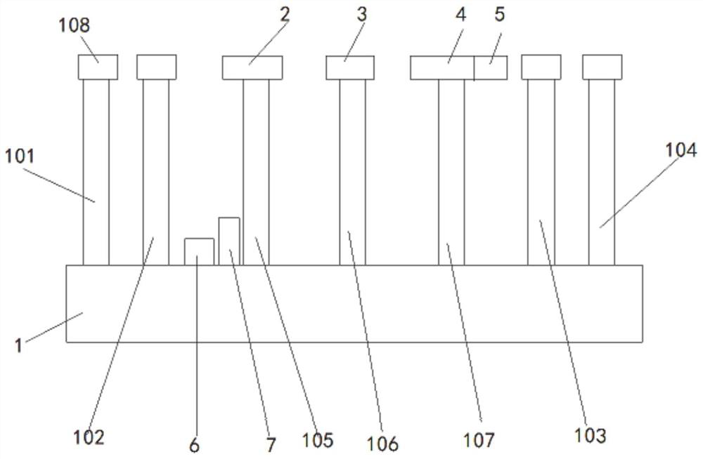
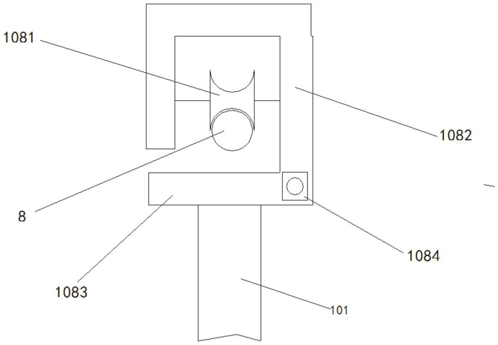
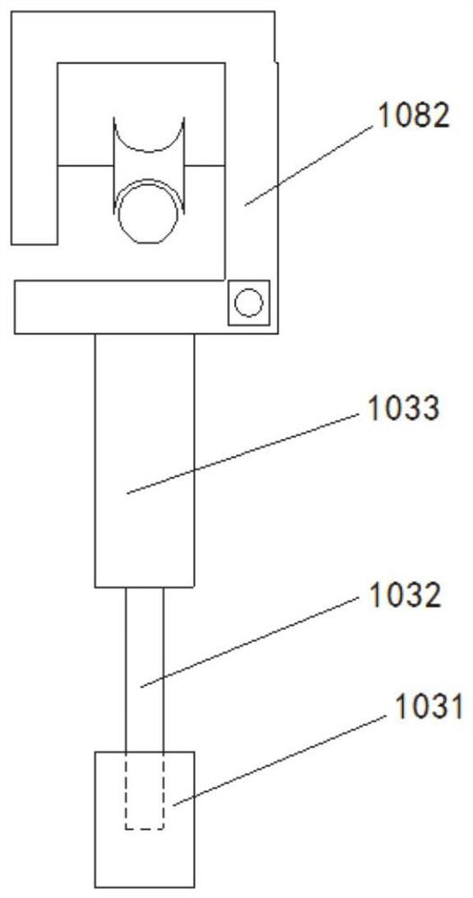
[0044] Such as figure 1 and figure 2As shown, a multifunctional power transmission line deicing device includes a platform 1, and a first telescopic rod 101, a second telescopic rod 102, and a third telescopic rod that are arranged on the platform from left to right in a straight line. 103, the fourth telescopic rod 104, the fifth telescopic rod 105, the sixth telescopic rod 106 and the seventh telescopic rod 107; the first telescopic rod 101, the second telescopic rod 102, the third telescopic rod 103 and the fourth telescopic rod The upper ends of 104 are equipped with a walking wheel structure 108, which can cooperate with or disengage from the high-voltage line 8 at any time. When encountering an obstacle, the obstacle-crossing function can be realized by disengaging from one walking structure in turn to ensure that the device can walk on the high-voltage line 8 .

[0045] As a specific implementation, such as figure 2 As shown, the walking device can be set as a stru...


PUM


Abstract

The invention discloses a multifunctional power transmission line deicing device, which comprises: a platform, wherein the platform is of a cuboid structure, one end of the platform is vertically provided with a first telescopic rod and a second telescopic rod, and the other end is vertically provided with a third telescopic rod and a fourth telescopic rod; a first mechanical mechanism arranged atone end, close to the second telescopic rod, of the platform through a fifth telescopic rod, wherein a deicing knife is arranged at one end; a heating mechanism arranged at the position, close to thefourth telescopic rod and far away from the second telescopic rod, of the platform through a sixth telescopic rod; a second mechanical mechanism arranged between the sixth telescopic rod and the third telescopic rod on the platform through a seventh telescopic rod, wherein a scrubbing part is arranged at one end; and a drying mechanism arranged at the end, away from a sixth walking mechanism, ofa second open cylinder device. According to the invention, mechanical deicing and heating deicing modes can be combined, and through the arrangement of the scrubbing part and the drying mechanism, thephenomenon that the high-voltage line is rapidly iced after deicing is avoided.

Description

technical field [0001] The invention belongs to the related technical field of power transmission line maintenance, and in particular relates to a multifunctional power transmission line deicing device. Background technique [0002] The statements in this section merely provide background information related to the present disclosure and do not necessarily constitute prior art. [0003] In the winter of our country, there is a lot of rain and snow in the north, and ice often occurs on the transmission line. If it is not cleaned up in time, it is easy to form an ice layer, which will increase the weight of the transmission line, break the transmission line, cause the circuit to be interrupted, and affect the normal life of the residents. Life. [0004] According to the knowledge of the inventor, the existing methods of removing ice on the transmission line include: manual beating, which is very labor-intensive, labor-intensive, and inefficient; mechanical deicing equipment, ...

Claims


Application Information

Patent Timeline
Patent Type & Authority Applications(China)
IPC IPC(8): H02G7/16F26B5/14F26B3/04F26B21/00
CPCH02G7/16F26B5/14F26B3/04F26B21/004
Inventor 洪军冯磊邱勇苏桂丰张长斌张建军蒋仲俊
Owner 国网山东省电力公司泗水县供电公司
Learn More