High-voltage transmission line deicing device

A high-voltage transmission line and ice-melting technology, applied in the installation of cables, electrical components, overhead installation, etc., can solve problems such as affecting the transmission efficiency of high-voltage lines, scratches and cracks in high-voltage lines

Inactive Publication Date: 2020-10-27
宋允华
View PDF0 Cites 4 Cited by
  • Summary
  • Abstract
  • Description
  • Claims
  • Application Information

AI Technical Summary

Problems solved by technology

[0003] The traditional deicing device generally adopts mechanical deicing, and removes the ice cubes on the high voltage line through ice equipment. Although the deicing efficiency is high, in actual use, especially when the ice cubes are thick, it will cause scratches on the surface of the high voltage line. Injury or even cracking, thus affecting the transmission efficiency of high-voltage lines

Method used


Image

  • High-voltage transmission line deicing device
  • High-voltage transmission line deicing device
  • High-voltage transmission line deicing device

Examples


Embodiment 1

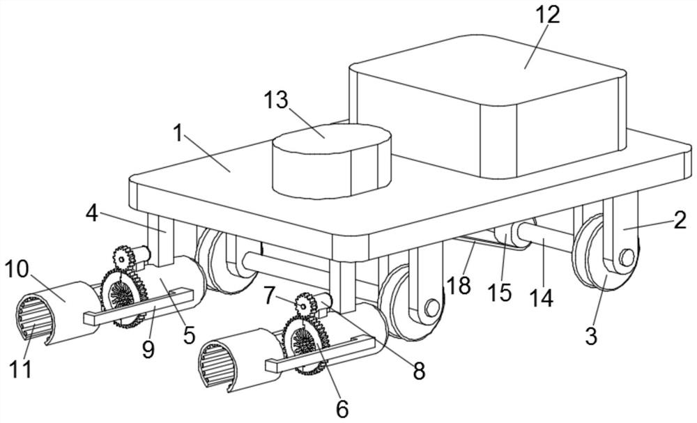
[0029] see figure 1 , a high-voltage transmission line deicing device, including a platform 1, the four corners of the lower end surface of the platform 1 are installed with rollers 3 through the rotation of the support 2, and the deicing mechanism is symmetrically installed on both sides of the front end of the platform 1, and the deicing mechanism It includes an ice-melting assembly and a cleaning assembly, and the ice-melting assembly and the cleaning assembly are fixedly connected through a connecting frame 9;

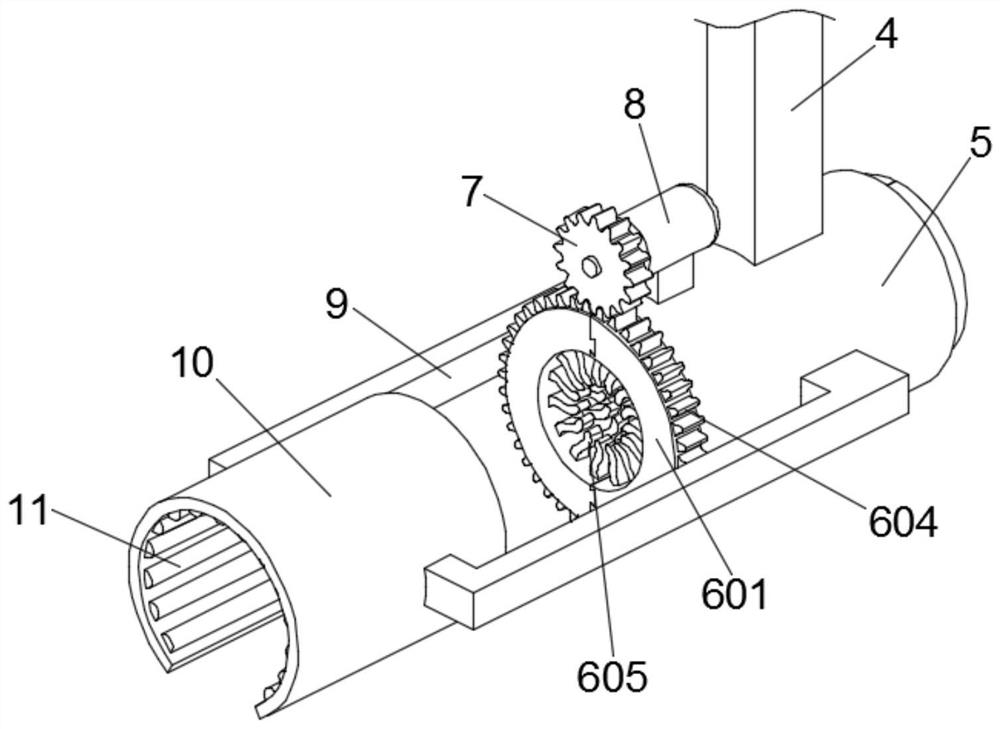
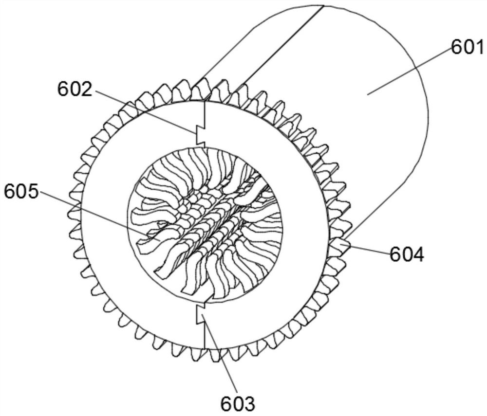
[0030] see Figure 2-3 , the ice-melting assembly includes a heating mantle 10, and a plurality of heating strips 11 are annularly arranged on the inner wall of the heating mantle 10; Fixedly installed on the lower end surface of the platform 1, the fixed sleeve 5 is rotatably provided with a cleaning cylinder 6, the cleaning cylinder 6 is formed by splicing two half cylinders 601, and the outer wall of one end of the cleaning cylinder 6 is provided with teeth Ri...

Embodiment 2

[0040] A high-voltage transmission line deicing device, including a platform 1, the four corners of the lower end surface of the platform 1 are rotated by a support 2, and rollers 3 are installed, and the two sides of the front end of the platform 1 are symmetrically installed with a deicing mechanism, and the deicing mechanism includes An ice-melting assembly and a cleaning assembly, the ice-melting assembly and the cleaning assembly are fixedly connected through a connecting frame 9;

[0041]The ice-melting assembly includes a heating cover 10, and a plurality of heating strips 11 are annularly arranged on the inner wall of the heating cover 10; the cleaning assembly includes a fixing sleeve 5 and a cleaning cylinder 6, and the fixing sleeve 5 is fixed by a fixing column 4 Installed on the lower end surface of the platform 1, the fixed sleeve 5 is rotatably provided with a cleaning cylinder 6, the cleaning cylinder 6 is formed by splicing two half cylinders 601, and a ring ge...


PUM


Abstract

The invention discloses a high-voltage transmission line deicing device which comprises a platform, rollers are rotatably mounted on the lower end face of the platform, deicing mechanisms are symmetrically mounted on the two sides of the front end of the platform, and each deicing mechanism comprises an ice melting assembly and a sweeping assembly. A driving mechanism for driving the rollers to roll is mounted on the lower end surface of the platform. A controller and a storage battery are arranged on the upper end surface of the platform. According to the high-voltage transmission line deicing device, ice blocks on a high-voltage line are heated and melted through the ice melting assembly, then the melted ice blocks are removed from the high-voltage line through the sweeping assembly which rotates annularly, and the deicing effect is good. The sweeping assembly can be rapidly disassembled and assembled, and is convenient to install, maintain and use. The driving mechanism drives the roller to run along the high-voltage line, and the roller is provided with the annular groove, so that the roller is firmly clamped on the high-voltage line, platform rollover caused by separation of the roller and the high-voltage line is avoided, and overall stability and operation safety are improved.

Description

technical field [0001] The invention relates to the technical field of high-voltage line deicing, in particular to a high-voltage transmission line deicing device. Background technique [0002] In the field of high-voltage transmission line technology, the problem of tower poles falling and breaking due to icing on the line due to the inability to bear the pressure occurs from time to time, which causes major economic losses to the country every year, and also brings great inconvenience to people's lives. , so it is necessary to de-ice the high-voltage line to ensure the normal power transmission function of the high-voltage line. [0003] The traditional deicing device generally adopts mechanical deicing, and removes the ice cubes on the high-voltage line through ice tools. Although the deicing efficiency is high, in actual use, especially when the ice cubes are thick, it will cause scratches on the surface of the high-voltage line. Injury or even cracking, thus affecting ...

Claims


Application Information

Patent Timeline
Patent Type & Authority Applications(China)
IPC IPC(8): H02G7/16H02G1/02
CPCH02G1/02H02G7/16
Inventor 宋允华
Owner 宋允华
Why Eureka
Try Eureka