
Optical screening machine for parts

A technology for screening machines and components, applied in the field of optical screening machines, which can solve the problems of inconvenient detection, scattered components, and inability to limit combing and transmission in the transmission structure, so as to achieve the effect of flexible and convenient transmission and avoid scatter

Inactive Publication Date: 2021-04-06
上海聚正智能科技有限公司
View PDF7 Cites 0 Cited by
  • Summary
  • Abstract
  • Description
  • Claims
  • Application Information

AI Technical Summary

Problems solved by technology

[0003] At present, the transmission structure between the screening structure and the detection structure of most optical screening machines is fixedly connected. During use, when the screening structure screens different types of parts, after screening, the transmission structure It is not possible to carry out good limit combing and transmission according to the type and size of the parts, and it is easy to cause the parts to be scattered during the transmission process, which makes the detection more inconvenient. Therefore, we have designed an optical sensor for parts. Screening machine to solve the above problems

Method used

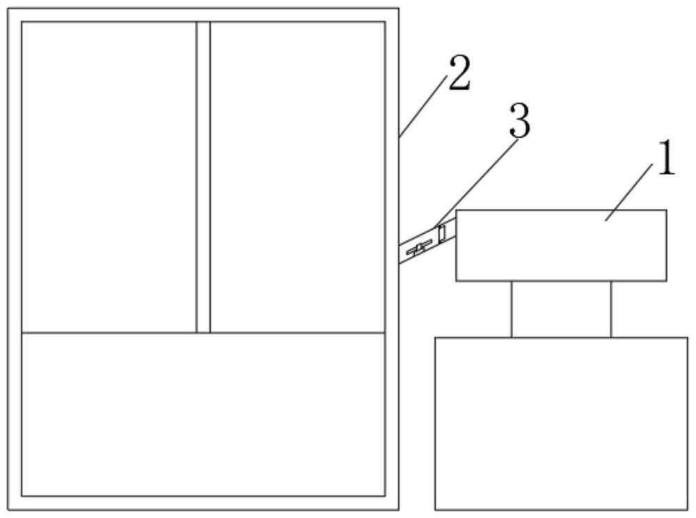

Image

  • Optical screening machine for parts
  • Optical screening machine for parts
  • Optical screening machine for parts

Examples


Embodiment 1

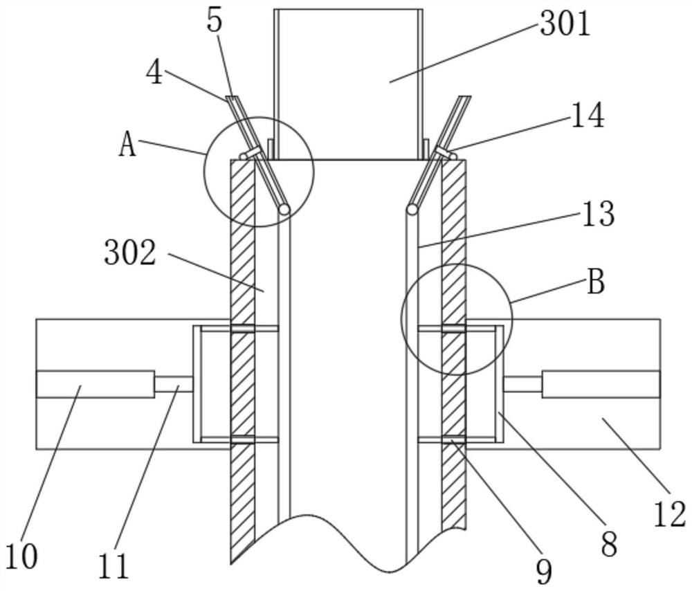
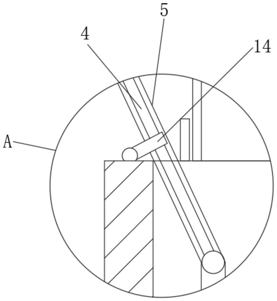
[0026] refer to figure 1 , figure 2 with Figure 4 , an optical screening machine for parts, including a body, the body includes a screening structure 1, a detection structure 2 and a transmission structure 3, the transmission structure 3 is connected between the screening structure 1 and the detection structure 2, and the transmission structure 3 includes an upper transmission Rack 301 and lower transfer rack 302;

[0027] Both sides of the upper transmission frame 301 are provided with a first baffle plate, both sides of the lower transmission frame 302 are provided with a second baffle plate, one end of the lower transmission frame 302 is provided with a fixed block on both sides, and the lower transmission frame 302 is fixed by The block is connected with the upper transmission frame 301, and the second baffle plate on both sides of the upper transmission frame 301 is connected with a fixed plate 12, and the two fixed plates 12 are equipped with push rod motors 10, and ...


PUM


Abstract

The invention discloses an optical screening machine for parts, and relates to the technical field of optical screening machines. The optical screening machine comprises a machine body, the machine body comprises a screening structure, a detection structure and a conveying structure, the conveying structure is connected between the screening structure and the detection structure, and the conveying structure comprises an upper conveying frame and a lower conveying frame; and first baffles are arranged on the two sides of the upper conveying frame correspondingly, second baffles are arranged on the two sides of the lower conveying frame correspondingly, fixing blocks are arranged on the two sides of one end of the lower conveying frame correspondingly, and the lower conveying frame is connected with the upper conveying frame through the fixing blocks. When the optical screening machine is used, through the adjustable design of the conveying structure, when different parts are conveyed, the distance between two limiting plates can be adjusted according to the types and sizes of the models of the conveyed parts, the screened parts are better sorted, detection is more convenient, use is more flexible and convenient, and the optical screening machine is suitable popularization and application.

Description

technical field [0001] The invention relates to the technical field of optical screening machines, in particular to an optical screening machine for components. Background technique [0002] With the rapid development of my country's processing industry, parts are becoming more and more high-precision and practical. Therefore, the product quality requirements in the sales market are also constantly improving, and relying on manual service inspections seems dull and time-consuming. Therefore, there is an urgent need to replace manual inspection with accurate and fast automatic technology optical inspection equipment. [0003] At present, the transmission structure between the screening structure and the detection structure of most optical screening machines is fixedly connected. During use, when the screening structure screens different types of parts, after the screening, the transmission structure It is not possible to carry out good limit combing and transmission accordi...

Claims


Application Information

Patent Timeline
Patent Type & Authority Applications(China)
IPC IPC(8): B07C5/02
CPCB07C5/02
Inventor 杨彦恺
Owner 上海聚正智能科技有限公司
Learn More