Metal buckle stamping equipment for high-end equipment manufacturing
A technology for metal buckles and stamping equipment, applied in metal processing equipment, manufacturing tools, feeding devices, etc., can solve the problems of short service life, high cost, and plastic buckles are easily broken and deformed, saving manpower and improving work. The effect of efficiency
- Summary
- Abstract
- Description
- Claims
- Application Information
AI Technical Summary
Problems solved by technology
Method used
Image
Examples
Embodiment 1
[0071] A metal buckle stamping equipment for high-end equipment manufacturing, such as figure 1As shown, it includes a bottom plate 1, a bed frame 2, a stamping mechanism 3, a cutting mechanism 4 and a discharge mechanism 7, a bed frame 2 is arranged between the top of the right side of the bottom plate 1, and a rectangular hole is opened on the left side of the bed frame 2, and the bottom plate 1 There is a stamping mechanism 3 on the left rear side, the stamping mechanism 3 is located above the rectangular hole, the left side of the bottom plate 1 is provided with a cutting mechanism 4, the cutting mechanism 4 is located below the rectangular hole, and the top of the cutting mechanism 4 is equipped with a discharge mechanism 7 .
[0072] When people want to press the iron fast into a buckle, they first put the iron block on the 4 parts of the cutting mechanism, start the 3 parts of the stamping mechanism, press down on the 3 parts of the stamping mechanism, and press on the ...
Embodiment 2
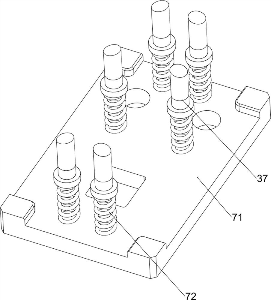
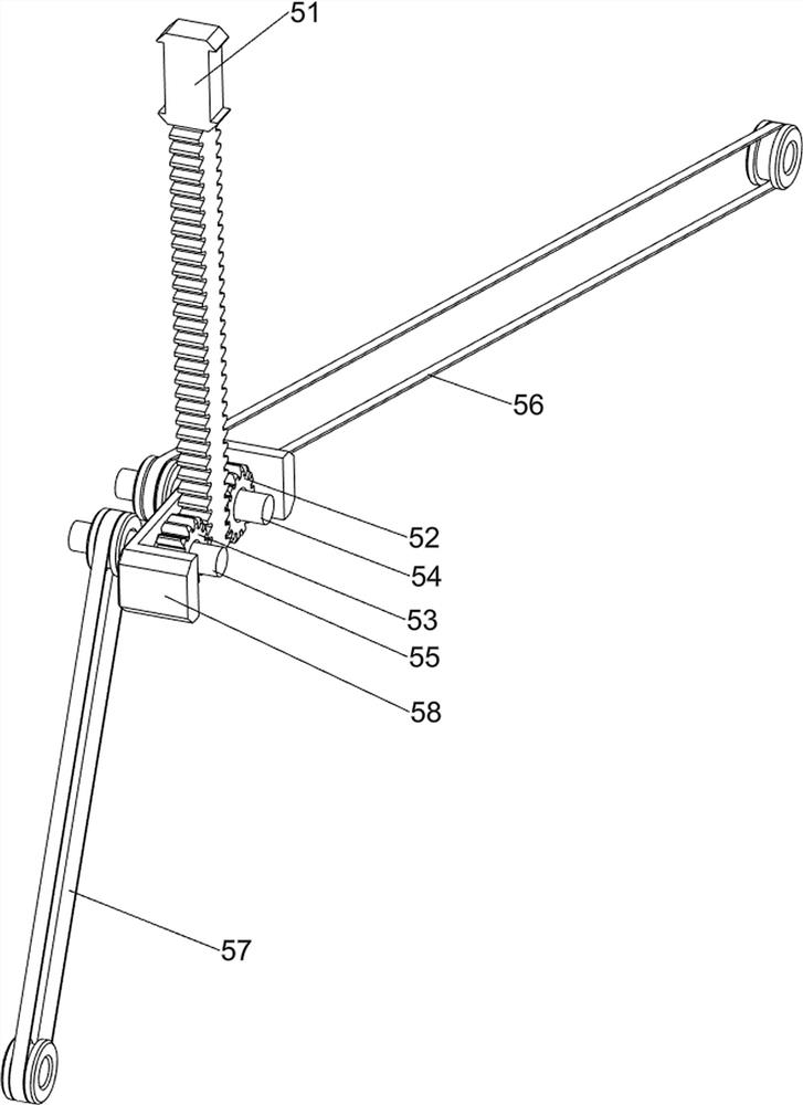
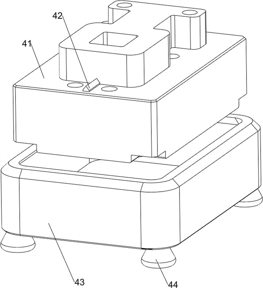
[0074] On the basis of Example 1, such as Figure 2-7 As shown, the stamping mechanism 3 includes a main bracket 31, a top plate 32, a cylinder 33, a mounting plate 34, a first bracket 35, a first thimble 36, a first ejector plate 37, a first screw 38 and an upper mold 39, and the bottom plate 1 Left rear side is provided with main support 31, and main support 31 upper front side is provided with mounting plate 34, and mounting plate 34 front sides are provided with first support 35, and first support 35 bottoms are provided with cylinder 33, and cylinder 33 telescoping rods pass through the second A support 35, a top plate 32 is provided on the top of the cylinder 33 telescopic rods, a patrix 39 is provided at the bottom of the rear side of the top plate 32, and the patrix 39 is slidably connected with the mounting plate 34, and the bottom of the mounting plate 34 is provided with four first thimbles 36, the second A first ejector plate 37 is slidably connected between the ej...
PUM
 Abstract
Description
Claims
Application Information
 - R&D
- Intellectual Property
- Life Sciences
- Materials
- Tech Scout
- Unparalleled Data Quality
- Higher Quality Content
- 60% Fewer Hallucinations
Browse by: Latest US Patents, China's latest patents, Technical Efficacy Thesaurus, Application Domain, Technology Topic, Popular Technical Reports.
© 2025 PatSnap. All rights reserved.Legal|Privacy policy|Modern Slavery Act Transparency Statement|Sitemap|About US| Contact US: help@patsnap.com


