A wood edge cutting equipment for furniture

A technology for cutting equipment and wood, which is applied to the field of wood edge cutting equipment for furniture, and can solve the problems of low safety, oblique placement in a working position, and trouble.

Active Publication Date: 2022-08-09
NANJING YUZHI INTELLIGENT TECH CO LTD
View PDF0 Cites 0 Cited by
  • Summary
  • Abstract
  • Description
  • Claims
  • Application Information

AI Technical Summary

Problems solved by technology

[0003] Some furniture manufacturers need to cut the corners of the wood when making furniture parts. The cutting method is to manually tilt the wood to a certain angle, and then manually push the wood block to the side of the cutting machine. Complete the corner cutting of the wood; there are three disadvantages of this method, one is: the wood needs to be placed obliquely on the working position manually, which is more troublesome, and the angle of inclination is different each time; the second is that when cutting the wood, manual pressing is required Cutting the corners of the wood is less safe; the third is that the wood needs to be pushed out manually after the wood is cut

Method used


Image

  • A wood edge cutting equipment for furniture
  • A wood edge cutting equipment for furniture
  • A wood edge cutting equipment for furniture

Examples


Embodiment 1

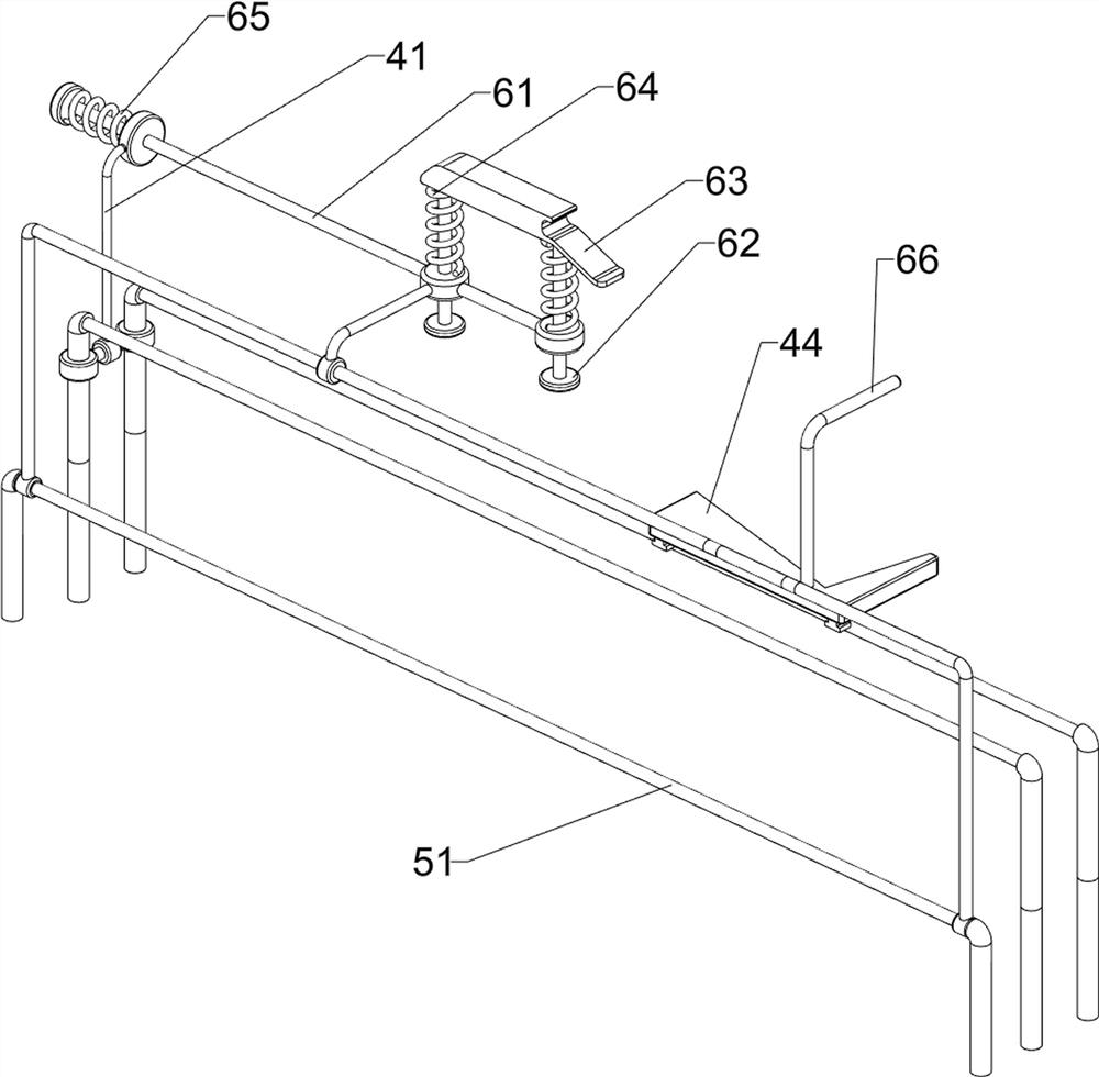
[0030] A wood edge cutting equipment for furniture, such as figure 1 and figure 2 As shown in the figure, it includes a base 1, a saw blade 2, a motor 3, a placement assembly 4 and a push assembly 5. The top left side of the base 1 is provided with a saw blade 2, the top front side of the base 1 is provided with a placement assembly 4, and the placement assembly 4 is placed on the left A motor 3 is provided on the base 1, and a push assembly 5 is provided on the front side of the top of the base 1. The push assembly 5 is located on the front side of the placement assembly 4, and the parts of the push assembly 5 are connected with the parts of the placement assembly 4.

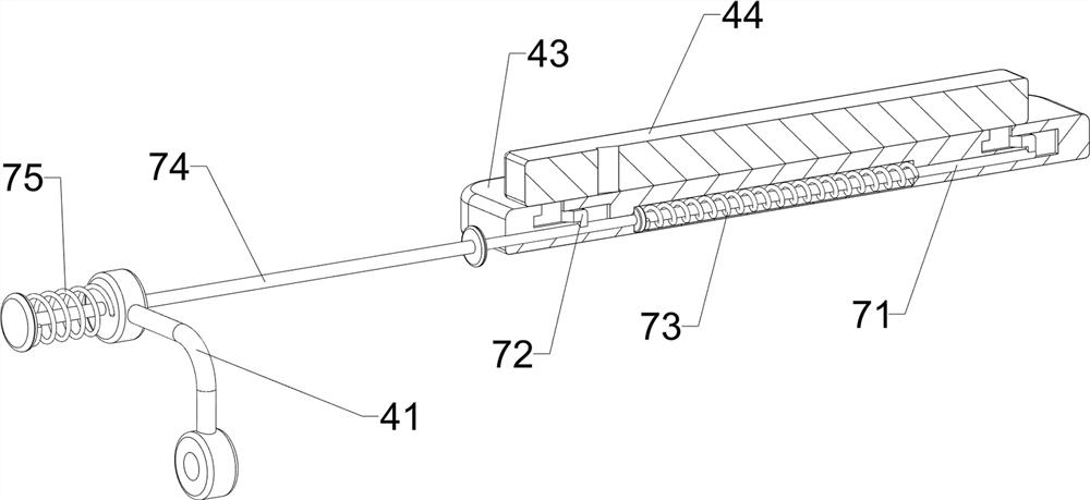
[0031] The placing assembly 4 includes a first supporting frame 41, a first connecting rod 42, a placing plate 43 and a push plate 44. A first supporting frame 41 is provided on the front side of the top of the base 1, and the motor 3 is located in the middle of the first supporting frame 41. The upper part o...

Embodiment 2

[0035] On the basis of Example 1, as figure 1 , image 3 , Figure 4 , Figure 5 , Image 6 , Figure 7 and Figure 8 As shown, it also includes a pressing assembly 6. The pressing assembly 6 includes a fourth connecting rod 61, a pressing rod 62, a first wedge block 63, a first spring 64, a second spring 65 and a fifth connecting rod 66. A fourth connecting rod 61 is slidably provided on the upper left side of the upper part of the support frame 41 , and two pressing rods 62 are slidably provided on the right side of the fourth connecting rod 61 . A first spring 64 is connected between both sides of the wedge block 63 and the fourth connecting rod 61 , a second spring 65 is connected between the left side of the fourth connecting rod 61 and the first support frame 41 , and the top of the push plate 44 is provided with a second spring 65 . The fifth link 66 is in contact with the first wedge block 63 .

[0036] It also includes a locking assembly 7. The locking assembly...


PUM


Abstract

The invention relates to a cutting device, in particular to a wood edge and corner cutting device for furniture. The technical problem to be solved is: to provide a wood edge cutting device for furniture, which can automatically feed the wood edge and corner before cutting, automatically clamp the wood edge and corner during cutting, and automatically push out the wood edge and corner after the wood edge is cut. A wood edge and corner cutting equipment for furniture, comprising: a base and a saw blade, the saw blade is provided on one side of the top of the base; a placement component, the placement component is provided on the top of the base; a motor, the placement The motor is provided on the assembly; the push assembly is provided, and the push assembly is provided on the side of the top of the base close to the placement assembly, and the parts of the push assembly are connected with the parts of the placement assembly. The invention achieves the effects of automatic feeding before cutting the wood edge, automatic clamping when the wood edge is cut, and automatic pushing out after the wood edge is cut.

Description

technical field [0001] The invention relates to a cutting device, in particular to a wood edge and corner cutting device for furniture. Background technique [0002] Furniture has continued to develop and innovate following the pace of the times. Today, there are many categories, different materials, complete varieties and different uses. It is an important foundation for building a working and living space. [0003] When some furniture manufacturers make furniture parts, they need to cut the corners of the wood. The cutting method is to manually place the wood at a certain angle, and then manually push the wood block to the side of the cutting machine. Complete the cutting of the edges and corners of the wood; there are three disadvantages of this method, one of which is that the wood needs to be placed in the working position manually, which is more troublesome, and the angle of each oblique placement is different; the second is that when the wood is cut, it needs to be p...

Claims


Application Information

Patent Timeline
Patent Type & Authority Patents(China)
IPC IPC(8): B27B5/04B27B5/29B27B31/00B27B31/08B27B29/02
CPCB27B5/04B27B5/29B27B31/00B27B31/08B27B29/02
Inventor 李显凤
Owner NANJING YUZHI INTELLIGENT TECH CO LTD
Why Eureka
Try Eureka