
Soil spreading device for geotechnical engineering

A technology of geotechnical engineering and paving, which is applied in soil protection, infrastructure engineering, construction, etc., can solve the problems of low laying efficiency, troublesome construction, and difficult dispersal of earthwork, so as to reduce the input of manpower and material resources, reduce the The use of mechanical equipment and the effect of avoiding the hidden danger of building dumping

Active Publication Date: 2022-02-08
WUHAN SURVEYING GEOTECHN RES INST OF MCC
View PDF5 Cites 0 Cited by
  • Summary
  • Abstract
  • Description
  • Claims
  • Application Information

AI Technical Summary

Problems solved by technology

[0003] In the foundation treatment process of existing construction projects, the bedding of the layer of soil is generally laid by hand, and the fill is transported to the construction area by the earth truck, and then laid manually. The laying efficiency is very low, and the fill is very expensive It is easy to cause uneven bedding. After laying, it needs to be rolled by rolling equipment, which is troublesome.
In addition to direct manual laying, there is also the use of earth trucks to transport the soil to the soil paving area, then dump it and push it away with a bulldozer, and then use rolling equipment to pave the soil and compact it. This method has the disadvantages that the soil is not easy to break up and Soil accumulation is not easy to be flattened, resulting in insufficient soil density, and this method also requires multiple manual assistance, the efficiency of soil laying is not very high, and more equipment and manpower are used, and the construction is more troublesome. Suitable for complex and changing construction workplaces

Method used


Image

  • Soil spreading device for geotechnical engineering
  • Soil spreading device for geotechnical engineering
  • Soil spreading device for geotechnical engineering

Examples


Embodiment Construction

[0024] The present invention will be further described below in conjunction with drawings and embodiments. attached Figure 1 to Figure 5 All are drawings of embodiments, drawn in a simplified manner, and are only used for the purpose of clearly and concisely illustrating the embodiments of the present invention. The following technical solutions shown in the drawings are specific solutions of the embodiments of the present invention, and are not intended to limit the scope of the claimed invention. Based on the embodiments of the present invention, all other embodiments obtained by persons of ordinary skill in the art without creative efforts fall within the protection scope of the present invention.

[0025] In the description of the present invention, it should be understood that the orientations or positional relationships indicated by the terms "upper", "lower", "inner", "outer", "left", "right" etc. are based on those shown in the accompanying drawings. Orientation or ...


PUM


Abstract

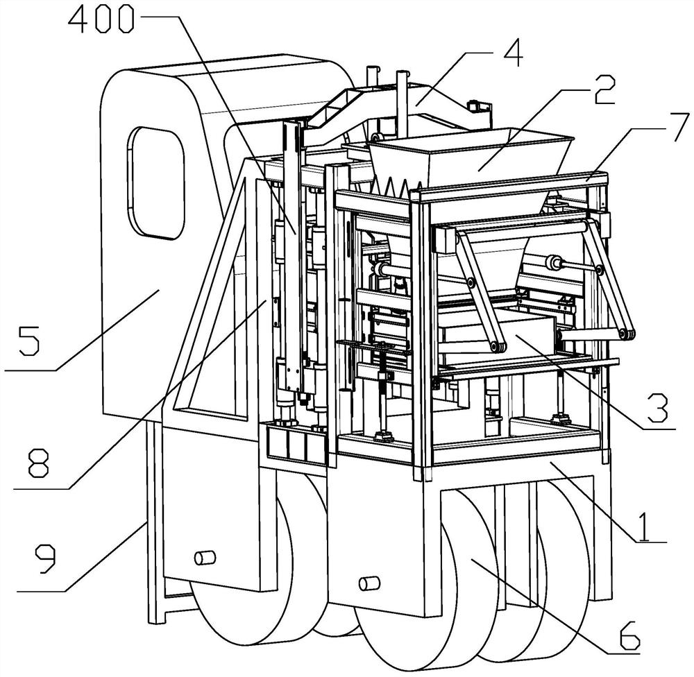
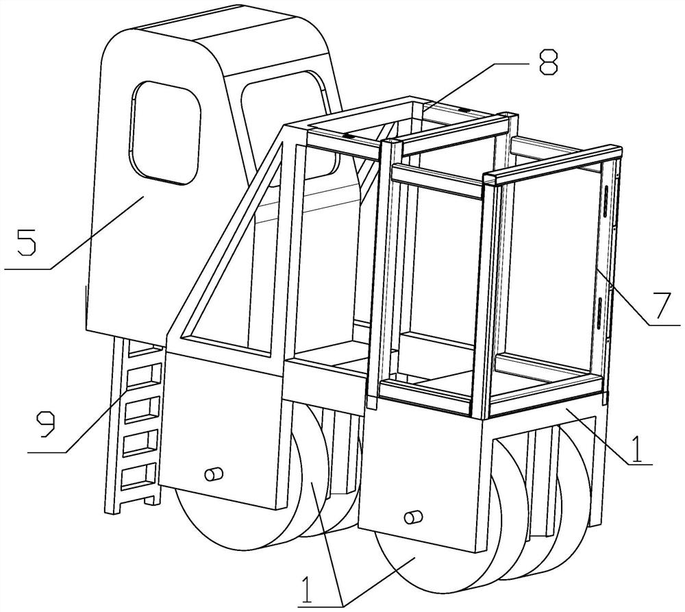
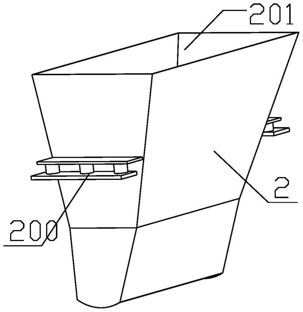
The invention provides a layer soil pressing device used in geotechnical engineering. The bedding device includes a walking mechanism, a layer soil injection bucket, a layer soil dumping module and a layer soil compaction module, and the running mechanism includes a cockpit, a walking chassis and a walking mechanism installed on the walking chassis, and the walking chassis There is a layer soil dumping module mounting frame and a layer soil compacting module mounting frame, and the layer soil compacting module mounting frame is placed behind the layer soil dumping module mounting frame; the layer soil dumping module is installed on the layer soil dumping module mounting frame It includes a support frame, a layer soil dispersion box and a turning and dumping mechanism; the layer soil compaction module is installed on the layer soil compaction module mounting frame, including a soil compaction block, a downward pressure cylinder, a cylinder mounting frame and a sliding frame. The invention integrates the functions of an earth truck, a bulldozer and a road roller, solves the problems of layer soil injection, layer soil dumping and layer soil compaction, has very high efficiency, and greatly improves work efficiency, ensuring that the soil surface of the paved soil layer is protected. Even force.

Description

technical field [0001] The invention relates to the technical field of construction engineering, in particular to a layer soil pressing device used in geotechnical engineering. Background technique [0002] In the field of construction engineering technology, the most important thing for the construction of buildings is to lay the foundation, and in the work steps of laying the foundation, the bedding of the layer of soil is also a very important part. It is necessary to ensure that the soil is evenly laid After the laying is completed, the soil layer needs to be rolled to ensure uniform compaction of the soil and uniform stress on the surface layer. If the stress on the foundation soil surface is uneven, it will directly affect the construction process of the later building. It may cause the collapse of the building. [0003] In the foundation treatment process of existing construction projects, the bedding of the layer of soil is generally laid manually, and the fill is t...

Claims


Application Information

Patent Timeline
Patent Type & Authority Patents(China)
IPC IPC(8): E02D3/00E02D3/02
CPCE02D3/00E02D3/02
Inventor 吴琪陈斌丁洪元叶坤刘耀峰
Owner WUHAN SURVEYING GEOTECHN RES INST OF MCC
Learn More