Public transport vehicle handrail convenient for different groups to hold

A technology of public transportation and handrails, which is applied to the special position of the vehicle, transportation and packaging, and vehicle parts, etc. It can solve the problems of difficult height adjustment, low applicable range, and poor applicability, so as to improve the degree of humanization, alleviate damage, Avoid the effect of insufficient support

Inactive Publication Date: 2021-04-13
孟思毅
11 Cites 0 Cited by

AI-Extracted Technical Summary

Problems solved by technology

[0003] The existing patent No. CN108437867B proposes a handrail device for urban buses, which has the advantages of simple disassembly and assembly and can be applied to passengers of different heights, but it is suitable for groups of different heights by setting two holding areas , its applicability to groups of different heights is...

Method used

Frame type handrail 6 inside is provided with elastic plate 8, and the top surface of elastic plate 8 is laid with ventilation hole 9, and the bottom surface of elastic plate 8 is fixedly connected with several depression bars 22, and the bottom surface of depression bar 22 is fixedly connected with piston A23, frame The positions corresponding to several pistons A23 on the inner wall of the bottom surface of the handrail 6 are all fixedly connected with a slide tube 24, the top surface of the slide tube 24 is i...

Abstract

The invention relates to the technical field of public transport means, and discloses a public transport vehicle handrail convenient for different groups to hold, which comprises a fixed column, a fixed rod is fixedly connected to the corresponding surface of the fixed column, a device rod is fixedly connected to the lower surface of the fixed rod, and the lower surface of the device rod is in a hollow state and is sleeved with a slender rod; the slender rod is fixedly connected with a plurality of limiting rods A, the right side wall in the device rod is fixedly connected with a device box, the device box is sleeved with a limiting rod B, the limiting rod B is sleeved with a torsional spring, the torsional spring is sleeved with a rotating column A, and the left side wall face of the limiting rod B is fixedly connected with a triggering rod. Through setting the slender rod, the height of a frame-shaped armrest is controlled through a simple operation. The public transport vehicle handrail meets the use requirements of different groups, prevents passengers from falling down due to congestion and the like caused by the fact that the passengers difficultly hold the frame-shaped handrail, improves the completeness and humanization degree of the public transport means, is high in operation efficiency, and can achieve automatic limiting without manual fixing and other operations.

Application Domain

Vehicle arrangements

Technology Topic

HandrailStructural engineering +3

Image

  • Public transport vehicle handrail convenient for different groups to hold
  • Public transport vehicle handrail convenient for different groups to hold
  • Public transport vehicle handrail convenient for different groups to hold

Examples

  • Experimental program(1)

Example Embodiment

[0031]The present invention will be further described below with reference to the accompanying drawings, in which the same components are indicated by the same reference numerals, it is to be explained, and the words "prior", "post", "left", "right", "right" are used in the following description. , "Upper" and "bottom" and "top" and "top" refer to the direction in the drawings, the words "inner" and "outside" refer to the direction or away from the specific component geometry center.
[0032]Next, the technical solutions in the embodiments of the present invention will be apparent from the embodiment of the present invention, and it is clearly described, and it is understood that the described embodiments are merely embodiments of the present invention, not all of the embodiments. Based on the embodiments of the present invention, there are all other embodiments obtained without making creative labor without making creative labor premises.
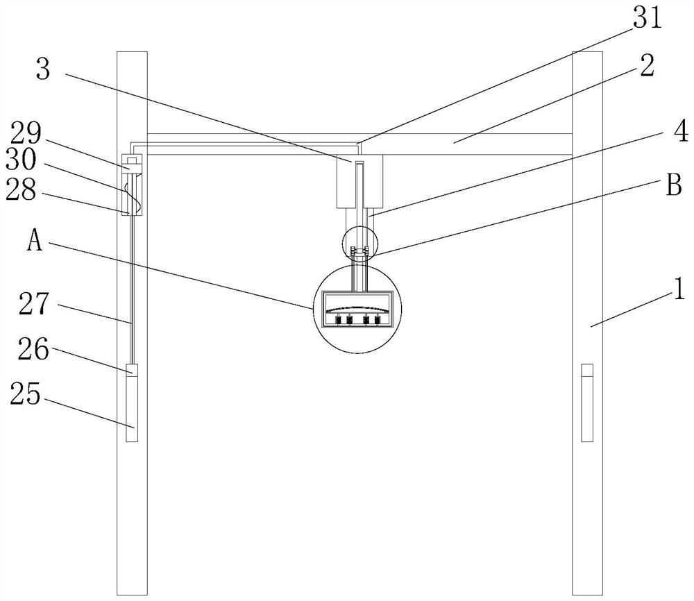
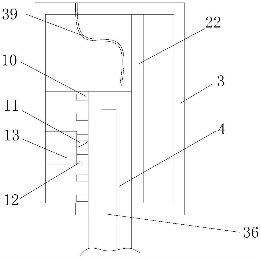
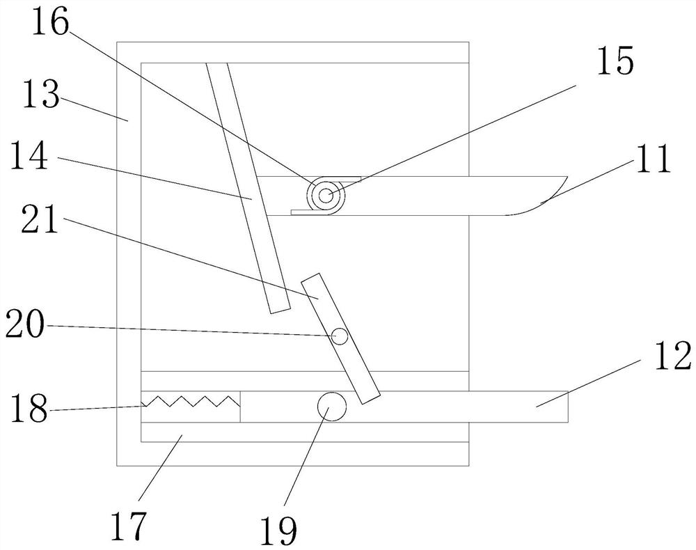
[0033]SeeFigure 1-7The present invention provides a technical solution: a public transport armrest that facilitates the support of different groups, including fixed column 1, two fixed columns 1 and left and right alignment, fixed column 1 fixed surface fixed connection with fixed bar 2 The lower surface of the fixing lever 2 is fixedly connected to the device rod 3, and the lower surface of the device rod 3 is hollowed and sleeves to have a thin rod 4, and the thin rod 4 is fixed to the left side wall fixed connection between the device rod 3. The rod A10, the right side wall of the inside of the device rod 3 fixedly connected to the apparatus tank 13, and the device tank 13 is adjacent to the side of the restricted rod A10 in a hollow state and is sleeved into the finite rod B11, and the limit rod B11 is located inside the device box 13. The hole is opened and a torsion spring 16 is opened. The torsion spring 16 is sleeved in the positive surface of the transfer column A15, and the front side of the transfer column A15 is fixed in a fixed connection relationship. The left side wall surface of the limit rod B11 is fixed. The trigger rod 14, the trigger lever 14 is inclined and the top surface and the upper surface of the top surface are in the upper surface of the limit rod B11, and the upper surface of the outer end of the device tank 13 is attached to each other, and the device box 13 is inside. The front surface is fixedly connected to the transfer column B20, and the transfer column B20 is sleeved into the rotor 21, and the left side walls inside the apparatus tank 13 are fixedly connected to the two balance plates 17, and the cross section of the balance plate 17 is rectangular and the upper and lower alignment, the balance sheet 17 of the corresponding surface magnetic force connection finite rod C12, the left side wall surface of the limit rod C12 is fixedly connected to the spring B18, the spring B18 and the inside of the inside of the device tank 13 are fixed to the connection relationship, and the front side fixed connection of the limit rod C12 is short. The column 19, the limit rod C12 is located directly below the limit rod B11, and the bottom of the thin rod 4 is fixedly connected to the connecting rope 5, and the bottom portion of the connecting rope 5 is fixedly connected with the frame-shaped armrest 6. On the public transport, passengers according to their own The height can be highly adjusted to the fine rod 4, first move the fine rod 4, the limit rod A10 will squeeze the limit rod B11, and the limit rod B11 is squeezed, the limit rod B11 will be rotated around. The column A15 rotates, at which point the trigger lever 14 will hit the rotary rod 21, the rotary rod 21 will rotate about the transfer column B20, and the rotor 21 will collide with the short column 19, and the short column 19 will move to the left. The fine rod 4 is pulled down quickly, the thin rod 4 will fall, the limit rod C12 does not limit the limit rod A10 in a short time, at which time the spring B18 is elastic, the limit rod C12 is restored to the original position. The limit rod A10 is limited, and due to the action of the torsion spring 16, the limit rod B11 will restore the original position, continue to perform the signal limit bits of the limit rod A10, and utilize simple operations To the high level of the box, adapted to the needs of different groups, avoiding the fell of the passengers to support the figures of the frame, improve the perfection and humanity of public transport, and operational efficiency. High, no need to manually fix the operation, automatic limit, and the passengers will hold the armrest when the operation, even if the public transport in the process, the passengers have also taken the handrail, avoid the problem of the problem, etc. The setting of the limit rod B11 and the limit rod C12 is simultaneously supported and contracted by two sets of linkaged limit rods, and the pressure of the fine rod 4 is shared, and the ability to increase the fine rod 4 is increased, and the single limit is avoided. The appearance of problems such as lack of support for bit rods.
[0034]An elastic plate 8 is disposed inside the frame, and the top surface of the elastic plate 8 is laid, and the bottom surface of the elastic plate 8 is fixedly connected with several pressure rods 22, and the pressure rod 22 is fixedly connected to the piston A23, the frame handrail 6. The inner wall of the bottom surface corresponds to the position of the piston A23, and the slider 24 is fixed. The top surface of the slider 24 is in a hollow state and is inserted with the piston A23, and the piston A23 is fixedly connected to the spring A7, by spring A7 and the elastic plate 8. The settings are buffered by their own deformation, thereby causing a large pressure of the passenger handle 6, which can alleviate the damage to the passenger hand in the passenger imbalance, and further increase the public. The degree of humanity of the vehicle.
[0035]The fixing column 1 is opened on the front of the slot 25, and the slot 25 is sleeved in the slide 26, and the inside of the fixing column 1 is in a hollow state over the chute 25, and the inner wall of the bottom surface is fixedly connected to the rod 28, the outer wall of the sleeve 28 The piston B29 of the circular ring is fixed to the bottom surface of the piston B29, and the drawstring 27 and the spring C30 are fixed, and the drawing rope 27 is distinguished from the first end of the piston B29 through the fixed column 1 and is fixed to the slider 26, and there are two air holes in the inside of the fixed bar 2. A31, and the two air holes A31 communicate with the top surfaces at the interior of the two fixed column 1, and there is a groove in front and rear sides of the fine rod 4 and the trough 36 in the groove 36, and the device rod 3 corresponds to the position of the lever 36. In the hollow state, the fine rod 4 has a round slot in the position of the bottom end of the lever 36, and the groove is sleeved in the groove 33, and the pulling shaft 33 and the respective position of the pull rod 36 are fixedly connected by rotating the bearing, and the rotating shaft 33 away from one end of the lever 36. In the outer wall of the fine rod 4, the rotor 32 is fixed, and the shaft 33 is fixed to the outer wall of the drum 32, and the air hole A31 is fixedly connected to one end of the fixed column 1, and the two trachea C39 away from the air hole A31. One end is located in the pressure rod 22 and communicated with the fine rod 4 on the right side before and after the fine rod 4, first pull the slider 26 to slide it in the chute 25, the slider 26 pulls the piston B29 in the sleeve 28 Slide, and cause a negative pressure above the inside of the fixed column 1, the negative pressure is pulled by the air hole A31 and the trachea C39 to form air flow, and the air flow is thrown to the fan plate 34, and the fan plate 34 drives the shaft. 33 Turn, the shaft 33 rotates the pulling rod 36 to flip the lever 4, and then the passenger can carry the fine rod 4 by the reference tie rod 36 to perform a high degree of adjustment operation. When the passenger looses the slider 26, the spring C30 drives the slider 26 and The piston B29 is reset, and the air inside the fixed column 1 is injected into the rotary barrel 32, and the plate 34 is reset by the test pressure of the injection air, by the arrangement of the lever 36, when the passenger is difficult to operate to the frame handrail 6 The tie rod 36 can be removed by a simple operation, thereby changing the fine rod 4 at a high degree of adjustment operation, which is convenient to further improve the portability and adaptability of the device to further improve the portability and adaptability of the device.
[0036]The interior of the frame handle 6 has a ring air hole B41. The bottom surface of the slider 24 is opened and the air hole B41 is connected. The frame handle 6 is fixedly connected with four trachea A37, and the four tracheal A37 is two or two front and rear distribution and all Connect with the air hole B41, the four trachea A37 is fixed to the first end of the frame armrest 6 and the fine rod 4 is fixed and the four drums 32 are respectively, respectively, and when the passenger does not balance the elastic plate 8, when the physical imbalance causes a large pressure to the elastic plate 8, The elastic plate 8 is slid in the slider 24 and the air in the slider 24 is extruded into the air hole B41, and then the air is injected into the drum 32 through the air hole B41 and the trachea A37, and the fan board 34 is injected into the air. Pushing the pulling rod 36 to flip, thereby placing the passenger's body to block the problem, avoiding the problem of the passenger falls due to the imbalance of the body, and the passenger can also support the tensile rod 36 through the body or hand, and the air pressure in the slider 24 is only The sufficient tensile 36 is up to 90 degrees, avoiding collision to the passengers, by the arrangement of the lever 36, when the passenger is unable to cause a lower-cutting force, and can be applied to the elastic plate 8 to press the lever 36 Put it, then supported from the body or hand to the tensile rod 36, thereby increasing the stability of the multiplication, preventing the body imbalance, resulting in a condition of falling due to collision or crowding, by the arrangement of the lever 36, when the passenger does not balance, pull rod 36 Automatically put down to the passenger's body to block, avoiding problems that passengers fall due to imbalance, increase the protection of passengers.
[0037]The interior of the frame handle 6 is opened, and the elastic plate 8 is fixedly connected and connected in communication with the tracheal D40. The two trachea D40 communicate with the air hole C42, and the frame handle 6 is fixed to the four trachea B38, The four tracheal B38 is connected to the two or two, and each is in communication with the pores C42, and the four trachea B38 is fixed to one end of the frame handle 6 and the fine rod 4 is fixedly coupled to the fine rod 32, respectively, and the fan panel 34 passes through the elastic ball. 35 is fixed to the shaft 33, and the inner wall of the drum 32 is provided with a plane, and the trachea B38 is located at the plane of the drum 32 in the inner wall of the drum 32 to the surface of the surface, the inner wall of the drum 32 is on both sides of the trachea B38. All holes are opened and the holes are penetrated, and the sector 34 is rotated to the plane as the rotating shaft 33 is rotated to the plane, thereby extruding the air between the fan panel 34, then fan When the plate 34 is rotated to the position of the counterpart B38, the gap between the sectors 34 increases and generates a negative pressure to pass the air tube B38 communicating with the elastic plate 8, so that the tip of the elastic plate 8 is made. The suction, suction acts to the hand of the passenger, so that when the passenger is applied to the rotating shaft 33 to rotate on the elastic plate 8, the hand is further fixed by the suction, through the air tube B38, when the passenger pair 8 When it is proposed, the suction is conducted to the passenger hand through the elastic plate 8, and use the suction to further fix the hand of the passengers, thereby further increasing the seating stability of the passenger to the armrest, and avoiding the hand of the passenger's body is unbalanced. Problems caused by the handle and falling from the handle.
[0038]Working principle: S1, on public transport, passengers can be highly adjusted to the fine rod 4 according to their own height, first move the fine rod 4, the limit rod A10 will squeeze the limit rod B11, limit pole After B11 is squeezed, the limit rod B11 will rotate about the transfer column A15, at which time the trigger lever 14 will hit the rotary rod 21, the rotary rod 21 will rotate around the transfer column B20, the rotary 21 will The collision short column 19, the short column 19 will move to the left. At this time, the thin rod 4 is quickly down, the thin rod 4 will fall, the limit rod C12 does not limit the limit rod A10 in a short time, this Due to the elastic force of the spring B18, the limit rod C12 returns to the original position, the limit rod A10 is limited, and the limit rod B11 will restore the original position due to the action of the torsion spring 16, and the limit rod A10 is continued Limited bit.
[0039]S2, first pull the slider 26 to slide it in the slot 25, the slider 26 pulls the piston B29 slid on the sleeve 28, and causes a negative pressure above the internal space of the fixed column 1, and the negative pressure passes through the air hole A31 and trachea. The C39 extracts the air within the drum 32 and forms air flow, the air flow generates the thrust, the fan plate 34 rotates, the rotating shaft 33 rotates the pulling rod 36 to flip the rod 4, then passengers can pass the reference rod 36 Bring the fine rod 4 to perform a high degree of adjustment operation, when the passenger releases the slide rod 26, the spring C30 drives the slider 26 and the piston B29 to reset, and injects the air inside the fixed column 1 into the rotoring barrel 32, the fan board 34 is injected The test pressure of the air trump rod 36 reset.
[0040]S3, when the passenger applies a large pressure to the elastic plate 8 due to the imbalance of the body, the elastic plate 8 is sliding in the slider 24 and extrudes the air in the slider 24 into the air hole B41, and the air passes The air hole B41 and the trachea A37 are injected into the drum 32, and the fan plate 34 is pushed to the push rod 36 that is injected into air, thereby playing the passenger's body to prevent the passenger to fall due to the body imbalance, passengers can also The body or hand is supported onto the tensile rod 36, and the air pressure in the slider 24 is only enough to flip the rod 36 to more than 90 degrees, avoiding collision to passengers.
[0041]S4, the fan board 34 is rotated at the plane as the rotating shaft 33 is rotated to the plane, thereby extruding the air between the fan board 34, and then the fan plate 34 rotates to the position of the corresponding trachea B38. When the gap between the sector 34 will increase and generate a negative pressure to extract air by connecting the air tube B38 communicating with the elastic plate 8, thereby generating suction, suction to passengers. The hand is further secured by the plenometer when the passenger is applied to the elastic plate 8 to rotate on the elastic plate 8.
[0042]While the embodiments of the invention have been shown and described, these examples may be made to make a variety of changes, modifications, and replacement without departing from the principles and spirit of the present invention, without departing from the spirit and spirit of the present invention. And variations, the scope of the invention is defined by the appended claims and their equivalents.

PUM

no PUM

Description & Claims & Application Information

We can also present the details of the Description, Claims and Application information to help users get a comprehensive understanding of the technical details of the patent, such as background art, summary of invention, brief description of drawings, description of embodiments, and other original content. On the other hand, users can also determine the specific scope of protection of the technology through the list of claims; as well as understand the changes in the life cycle of the technology with the presentation of the patent timeline. Login to view more.

Similar technology patents

Statistical method and device for user behavior data

Owner:WUHAN DOUYU NETWORK TECH CO LTD

Hotel vehicle booking method and system

InactiveCN105095979AReduce user inputImprove operational efficiency
Owner:CHUANCHENG CULTURE & MEDIA SHANGHAI

Information processing method, electronic device and system

ActiveCN103986502AImprove operational efficiencyGuaranteed experience
Owner:LENOVO (BEIJING) CO LTD

Cross-industry data resource integration system based on big data

InactiveCN110147400AReduce logistics costsImprove operational efficiency
Owner:QI AUTOMOTIVE CO LTD

Frequency adjusting method and device of frozen water pump and air conditioning system

PendingCN108775661ASolve high energy consumptionImprove operational efficiency
Owner:GREE ELECTRIC APPLIANCES INC OF ZHUHAI

Classification and recommendation of technical efficacy words

  • Improve operational efficiency

Alarm association rule obtaining method of mobile internet

ActiveCN102098175AAccurate resultsImprove operational efficiency
Owner:INSPUR TIANYUAN COMM INFORMATION SYST CO LTD

Automatic robot, control device and control method

Owner:BEIJING XIAOMI MOBILE SOFTWARE CO LTD +1

Operation processing method and device

Owner:BUBI BEIJING NETWORK TECH CO LTD

Automatic guided vehicle (AGV) scheduling control system

InactiveCN109669456AImprove operating system efficiencyImprove operational efficiency
Owner:WUHU HIT ROBOT TECH RES INST
Why Eureka
Try Eureka