
Hoisting tackle self-lubricating device based on use frequency and strength

A lifting block and self-lubricating technology, which is applied in the direction of load block, engine lubrication, quantitative device, etc., can solve the problems of lifting block service life, damage, accidents, etc., so as to save manual lubrication, increase lubrication frequency, The effect of ensuring safety

Inactive Publication Date: 2021-04-13
南京尔汇普商业有限公司
View PDF0 Cites 2 Cited by
  • Summary
  • Abstract
  • Description
  • Claims
  • Application Information

AI Technical Summary

Problems solved by technology

[0002] The lifting block is an important lifting tool. In order to ensure the normal operation of the lifting block, it is necessary to regularly lubricate the pulley bearing part of the lifting block. The current lubrication method is still carried out manually. On the one hand, it is manually lubricated regularly. It is more troublesome, and whether the lubrication of the block should be judged according to the frequency and strength of the block. If lifting heavy objects, it will cause greater friction, resulting in higher temperature, and the consumption of lubricant will be reduced. Then it will increase, if you still rely on regular lubrication, it will affect the service life of the lifting block, and even cause damage to the block due to severe wear, which will cause accidents

Method used


Image

  • Hoisting tackle self-lubricating device based on use frequency and strength
  • Hoisting tackle self-lubricating device based on use frequency and strength
  • Hoisting tackle self-lubricating device based on use frequency and strength

Examples


Embodiment Construction

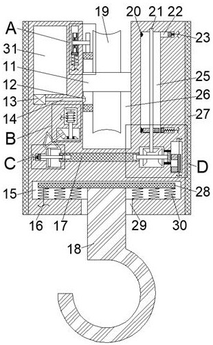
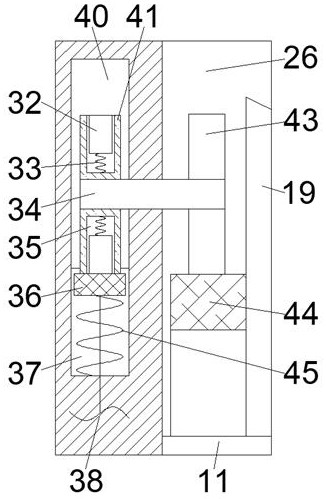
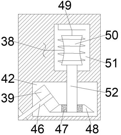
[0017] Combine below Figure 1-5 The present invention is described in detail, wherein, for the convenience of description, the orientations mentioned below are defined as follows: figure 1 The up, down, left, right, front and back directions of the projection relationship itself are the same.

[0018] A lifting block self-lubricating device based on the frequency of use and strength described in conjunction with accompanying drawings 1-5 includes a main body box 10, which is provided with a pulley chamber 26 with an opening upwards and through front and back, and the pulley A pulley shaft 11 is fixedly connected between the left and right end walls of the cavity 26, and a pulley 19 that is rotatably connected with the pulley shaft 11 is provided in the pulley cavity 26, and a weighing plate cavity 15 is provided on the lower side of the pulley cavity 26. The lower end wall of the weighing plate cavity 15 is connected with a hook cavity 29, the weighing plate cavity 15 is sli...


PUM


Abstract

The invention relates to the related field of cranes, and discloses a crane tackle self-lubricating device based on use frequency and strength. The self-lubricating device comprises a main body box, and a front-back through pulley cavity with an upward opening is arranged in the main body box; and a pulley shaft is fixedly connected between the left and right end walls of the pulley cavity, and a pulley in running fit connection with the pulley shaft is arranged in the pulley cavity. According to the crane tackle self-lubricating device, a centrifugal wheel is driven by the pulley to rotate, and meanwhile real-time recording of the use frequency of the pulley is achieved through a record sliding block capable of being moved up and down in a reciprocating mode along with the rotation frequency of the centrifugal wheel, and when the use frequency reaches a certain value, the miniature self-priming pump is automatically started and matched with a lubricating nozzle to lubricate a pulley bearing; a weight measuring plate is matched with a speed regulating cavity at the same time, so that the moving speed of the recording sliding block can be increased along with the increase of the weight of a lifted heavy object, namely, the lubricating frequency of the pulley is increased, and the lubrication of the pulley is more reasonable; and the safety of the lifting process is ensured, and meanwhile, the trouble of manual lubrication is further overcome.

Description

technical field [0001] The invention relates to the related field of cranes, in particular to a self-lubricating device for a lifting tackle based on frequency of use and strength. Background technique [0002] The lifting block is an important lifting tool. In order to ensure the normal operation of the lifting block, it is necessary to regularly lubricate the pulley bearing part of the lifting block. The current lubrication method is still carried out manually. On the one hand, it is manually lubricated regularly. It is more troublesome, and whether the lubrication of the block should be judged according to the frequency and strength of the block. If lifting heavy objects, it will cause greater friction, resulting in higher temperature, and the consumption of lubricant will be reduced. If it increases accordingly, if you still rely on regular lubrication, it will have an impact on the service life of the lifting tackle, and even cause damage to the tackle due to severe wea...

Claims


Application Information

Patent Timeline
Patent Type & Authority Applications(China)
IPC IPC(8): B66C11/00B66C1/34B66C13/16F16N7/30F16N7/38F16N27/00F16N21/00
CPCB66C1/34B66C11/00B66C13/16F16N7/30F16N7/38F16N21/00F16N27/00F16N2210/14
Inventor 张朋
Owner 南京尔汇普商业有限公司
Learn More