High-slot-space-factor rotor coil rack with self-locking collapse prevention function
A rotor coil and anti-collapse technology, applied to electrical components, electromechanical devices, windings, etc., can solve problems such as unstable generator performance and easy grounding of rotor coils, to ensure motor safety and production safety, and improve work stability Effect
- Summary
- Abstract
- Description
- Claims
- Application Information
AI Technical Summary
Problems solved by technology
Method used
Image
Examples
Embodiment 1
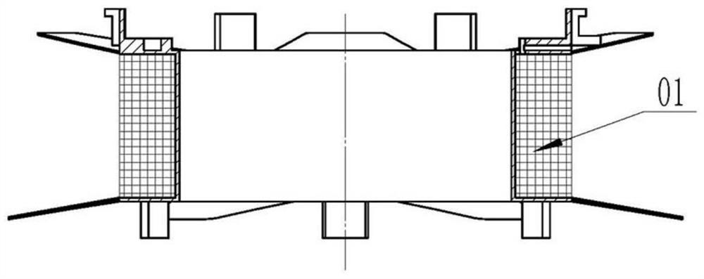
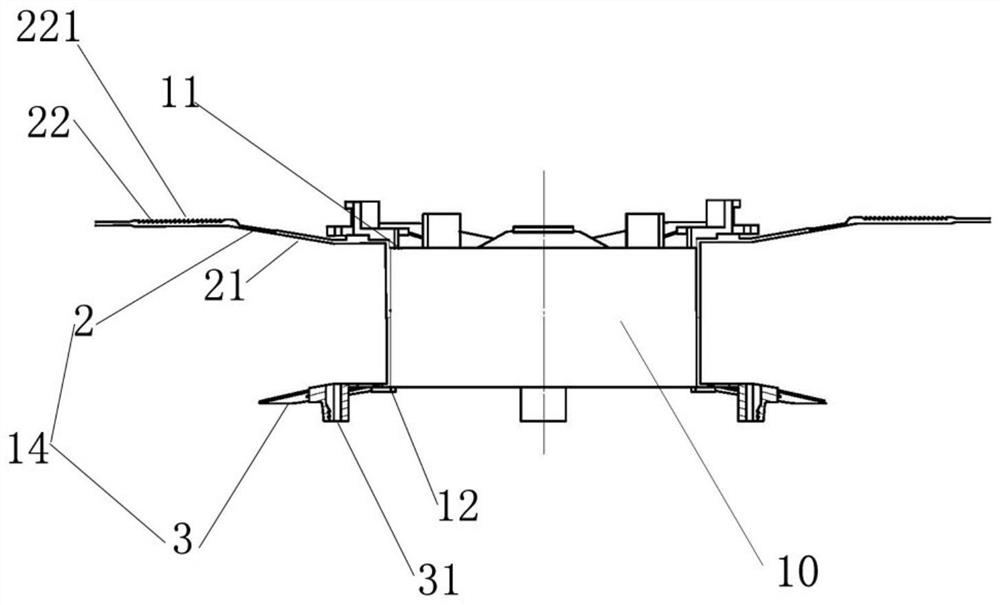
[0026] Such as Figure 2-6 As shown, a high-slot full-rate rotor former with self-locking anti-collapse function includes a central winding column 10, an upper stop plate 11 arranged at the upper end of the central winding column 10, and an upper stop plate 11 arranged at the lower end of the central winding column 10. The lower stopper 12 and the coil wrap protection mechanism 14 connected with the lower stopper 12 and the upper stopper 11.
[0027] The central winding column 10, the upper stopper 11 and the lower stopper 12 form a coil accommodation area, the coil accommodation area is the largest volume of the coil wound on the central winding column 10, the size of the coil accommodation area It is determined according to the size of the coil wound on the central winding column 10 , and the coil is determined according to the product specifications during actual production.
[0028] The coil wrapping protection mechanism 14 is used to wrap and protect the coil accommodati...
Embodiment 2
[0032] Based on embodiment 1, the difference from embodiment 1 is:
[0033] Such as figure 2 , image 3 As shown, the coil wrapping protection mechanism 14 includes a stopper 2 with one end disposed on the upper stopper 11 , and the other end of the stopper 2 is connected to a clip 3 arranged on the lower stopper 12 .
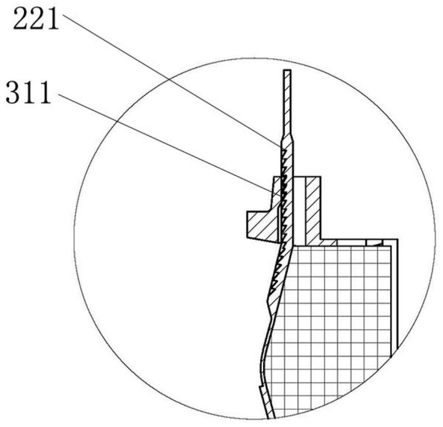
[0034] The blocking member 2 includes a folding blocking portion 21 that can be folded toward the clamping member 3. The end of the folding blocking portion 21 extends toward the clamping member 3 and is provided with a connecting portion 22, and the connecting portion 22 is connected to the locking member 3. The card firmware 3 is connected. The connecting portion 22 is provided with locking teeth 221, and the locking teeth 221 are inserted into the locking holes 31 provided in the clamping member 3, and can cooperate with the locking teeth 31 in the locking holes 31. The limiting teeth 311 of the teeth 221 are connected.
[0035] The blocking member 2 an...
Embodiment 3
[0037] Based on embodiment 1, the difference from embodiment 2 is:
[0038] Such as figure 2 , Figure 4 As shown, the folding blocking portion 21 is an elastic blocking portion, the connecting portion 22 includes a hook-shaped connecting head 222, and the locking member 3 is provided with an engaging groove 32 recessed toward the connecting portion 22. , the hook-shaped connecting head 222 can be connected with the engaging groove 32 and accommodated in the engaging groove 32 and fixedly limited by the engaging groove 32 .
PUM
 Abstract
Description
Claims
Application Information
 - R&D
- Intellectual Property
- Life Sciences
- Materials
- Tech Scout
- Unparalleled Data Quality
- Higher Quality Content
- 60% Fewer Hallucinations
Browse by: Latest US Patents, China's latest patents, Technical Efficacy Thesaurus, Application Domain, Technology Topic, Popular Technical Reports.
© 2025 PatSnap. All rights reserved.Legal|Privacy policy|Modern Slavery Act Transparency Statement|Sitemap|About US| Contact US: help@patsnap.com


