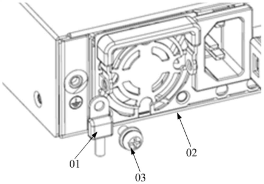
[0031]The present invention provides a grounding structure, which can reduce the occupied surface area of the electronic device, thereby more easily realizing the grounding of the electronic device, and better ensuring the normal operation of the electronic device.
[0032]The technical solutions in the embodiments of the present invention will be clearly and completely described below in conjunction with the accompanying drawings in the embodiments of the present invention. Obviously, the described embodiments are only a part of the embodiments of the present invention, rather than all the embodiments. Based on the embodiments of the present invention, all other embodiments obtained by those of ordinary skill in the art without creative work shall fall within the protection scope of the present invention.
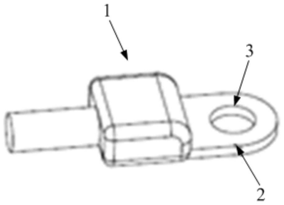
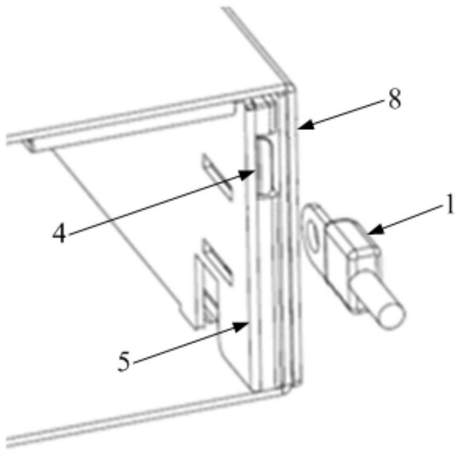
[0033]Such asFigure 2-Figure 7 As shown, the embodiment of the present invention provides a grounding structure, which can realize the grounding of electronic equipment, which mainly includes a grounding terminal 1 and a slot 4, where the grounding terminal 1 is an existing grounding terminal that meets industry standards , The ground terminal 1 has a sheet portion 2 for connecting with electronic equipment, and the sheet portion 2 is provided with a circular through hole 3, and the slot 4 is provided on the electronic device, and the slot 4 allows the sheet portion 2 Insertion. After the sheet 2 is inserted into the slot 4, the conductive connection between the housing 8 of the electronic device and the ground terminal 1 can be realized, that is, the grounding of the electronic device is realized, and the slot shape of the slot 4 Match the shape of the cross-section of the sheet-like portion 2, and the cross-section refers to the cutting surface formed by cutting the sheet-like portion 2 in a direction perpendicular to the sheet-like portion 2. When the sheet-like portion 2 is flat In the case of the sheet body, the cutting surface formed by cutting the sheet portion 2 in the direction perpendicular to the sheet portion 2 is a rectangular cross section. In this case, the shape of the notch is also rectangular, such asimage 3 Shown.
[0034]When using the above-mentioned grounding structure to realize the grounding of electronic equipment, first connect the wire connected to the ground terminal 1 to the ground, and then insert the piece 2 of the ground terminal 1 into the slot 4 opened on the electronic equipment. The grounding operation is completed. That is, the above-mentioned grounding structure requires only the slot 4 with a small opening area to be provided on the electronic device, so the occupation of the surface area of the housing 8 can be reduced, so that the grounding of the electronic device can be realized more simply, and the installation operation It only needs to be plugged in, without screwing the screws, and without using other accessories and tools to assist the operation, so that the grounding operation can be realized more conveniently and quickly.
[0035]In this embodiment, the slot 4 can be formed in a variety of options. In a preferred forming method, such asimage 3 As shown, a component 5 may be provided inside the housing 8, and the component 5 and the housing 8 enclose a slot 4. That is, a component (that is, the component 5, whose specific structure can be, for example, a plate-shaped member, a trough-shaped component, etc.) is arranged near the inner surface of the casing 8, so that the component and the inner surface of the casing 8 form a slot 4, The opening of the slot 4 is located at the corner of the housing 8. In addition, in another preferred forming method, the slot 4 can also be directly opened on the existing structure of the casing 8, that is, the slot 4 is formed inside the physical part of the casing 8.
[0036]Preferably, the depth direction of the slot 4 is parallel to the installation outer surface of the housing 8. This mounting outer surface specifically refers to the surface used to adhere to the ground terminal 1 in the prior art, that is, in this embodiment, when the slot 4 is provided, the component 5 is arranged parallel to the mounting outer surface (ieimage 3 The installation method shown) or open the slot 4 on the housing 8 parallel to the outer surface of the installation, so that the opening of the slot 4 can be located at the corner of the housing 8, so as to completely avoid the installation Occupation of the surface area of the outer surface. In addition, provided that the housing 8 has a sufficient thickness, the opening of the slot 4 can also be opened on the mounting outer surface, so that the sheet portion 2 of the ground terminal 1 can be inserted into the housing 8 perpendicular to the mounting outer surface. In this arrangement, since the area of the notch is still smaller than the area required for the attachment of the sheet portion 2 to the mounting outer surface, the grounding of the electronic device can also be achieved relatively easily.
[0037]Further, such asFigure 5-Figure 7 As shown, it is preferable that a pressing member 6 capable of elastic deformation is arranged in the slot 4, and the pressing member 6 can press the sheet portion 2 on the side wall of the slot 4 through elastic deformation. The grounding structure provided in this embodiment realizes the conductive connection between the ground terminal 1 and the electronic device by making the sheet portion 2 inserted into the slot 4 and the side wall of the slot 4 (this side wall can be the side wall of the housing 8). In order to ensure good contact between the two and improve the firmness of the contact between the two, a pressing member 6 is provided in the slot 4, which can be elastically deformed. 2 When inserted into the slot 4, the sheet portion 2 will occupy part of the space in the groove occupied by the pressing member 6, and then the pressing member 6 will be elastically deformed, while the elastically deformed pressing member 6 will The sheet portion 2 exerts elastic force to press the sheet portion 2 against the side wall of the slot 4, such asFigure 7 As shown, the sheet portion 2 is fully and firmly attached to the side wall of the slot 4, so that the ground terminal 1 will not be in good contact or separation with the electronic device due to vibration or impact, and thus the grounding structure Has a good conductive effect. Specifically, the pressing member 6 is preferably a metal shrapnel, such asFigure 5 withFigure 6 Shown.
[0038]More preferred, such asFigure 5-Figure 7 As shown, the slot 4 is provided with a locking member 7 that can extend into the through hole 3 to prevent the sheet portion 2 from falling out of the slot 4. While the sheet portion 2 is inserted into the slot 4 and pressed by the pressing member 6, the locking member 7 can extend into the through hole 3 to form a barrier to the sheet portion 2 so that the sheet portion 2 cannot The outward movement relative to the slot 4 can prevent the sheet portion 2 from falling out of the slot 4. Specifically, the structure of the locking member 7 can also have a variety of options, for example, it is a plug pin movably arranged in the slot 4, or it does not block the insertion of the sheet portion 2 but will prevent the sheet portion 2 from being detached. Form a blocking one-way stopper. By providing the locking member 7, the connection reliability between the ground terminal 1 and the electronic device can be further improved.
[0039]Specific, such asFigure 5-Figure 7 As shown, it is preferable that the locking member 7 realizes blocking and unblocking of the sheet portion 2 through elastic deformation, and the locking member 7 and the pressing member 6 are an integral structure, that is, the locking member 7 is arranged on the pressing member 6 The specific forming method of the locking member 7 can be to make the pressing member 6 (ie the metal elastic piece) partly tilted relative to the pressing member 6, such asFigure 6 withFigure 7 As shown, the end connected to the pressing member 6 does not form a barrier to the sheet portion 2, and the raised end does not block the insertion of the sheet portion 2, but blocks the escape of the sheet portion 2. In addition, the locking member 7 and the pressing member 6 may also be two independent components.
[0040]In addition, an unlocking member (not shown in the figure) for removing the locking member 7 from the through hole 3 may also be provided on the housing 8. The unlocking piece can be movably arranged on the housing 8. For example, one end of the unlocking piece extends into the slot 4 and is connected to the locking piece 7, and the other end extends to the outside of the housing 8, and the unlocking piece can be opposite to the housing 8. The body 8 expands and contracts. When the unlocking member is pressed to move it toward the inner side of the housing 8, the end of the unlocking member located in the slot 4 can drive the locking member 7 into the through hole 3 to realize the connection of the sheet portion 2 When the unlocking member is pulled to move it to the outside of the housing 8, the end of the unlocking member located in the slot 4 can drive the locking member 7 to move out of the through hole 3 to release the blocking of the sheet portion 2 , So that the sheet 2 can be manually or automatically removed from the slot 4. Alternatively, the grounding structure may not include an unlocking member. When the sheet portion 2 is inserted into the slot 4, the locking member 7 automatically blocks the sheet portion 2 in the slot 4 through elastic deformation, and the locking member 7 It is not possible to actively release the lock of the sheet part 2. When the operator needs to make the sheet part 2 to escape from the slot 4, the locking member 7 can be removed from the through hole 3 with a tool to release the blocking, such as operation A person can insert a flat-blade screwdriver into the slot 4 and press the elastically deformable locking member 7 to remove the locking member 7 from the through hole 3, and then the sheet portion 2 can be removed from the slot Pull out in 4.
[0041]In the specific setting, the constituent member 5, the pressing member 6 and the locking member 7 can be made into separate structures, and they can be assembled to the housing 8 one by one, that is, each part is an independent part and can be assembled one by one. The arrangement on the casing 8 is realized and the slot 4 is formed, or the component 5, the pressing member 6 and the locking member 7 can be connected in an integrated modular structure and assembled on the casing 8 at one time That is, the constituent member 5, the pressing member 6 and the locking member 7 can be pre-assembled as a whole, and then the whole is set on the housing 8 at one time to form the slot 4. Both of these two structures can be used for forming the slot 4 on the housing 8, so that the forming method of the slot 4 is more flexible and diverse.
[0042]In this specification, the structure of each part is described in a progressive manner. The structure of each part focuses on the difference from the existing structure. The whole and part of the grounding structure can be combined by combining the above-mentioned multiple parts. get.
[0043]The foregoing description of the disclosed embodiments enables those skilled in the art to implement or use the present invention. Various modifications to these embodiments will be obvious to those skilled in the art, and the general principles defined herein can be implemented in other embodiments without departing from the spirit or scope of the present invention. Therefore, the present invention will not be limited to the embodiments shown in this document, but should conform to the widest scope consistent with the principles and novel features disclosed in this document.