
Expandable stent having plurality of interconnected expansion modules

Inactive Publication Date: 2005-01-06
STENT TECH
View PDF12 Cites 96 Cited by
  • Summary
  • Abstract
  • Description
  • Claims
  • Application Information

AI Technical Summary

Benefits of technology

[0016] The alternate stents of the present invention are expandable, typically, for example, by enlarging an expandable balloon positioned within the stent, preferably having a plurality of expandable ring structures. The ring structures are joined end-to-end and feature an absence of potential tissue snagging structures. The stents and ring structures of the alternate stents are characterized by relatively low surface area compared to the surface area of a simple cylinder of similar dimensions and connecting structures, which allow the various ring structures to articulate with respect to one another. The stents of the present invention are efficiently and easily produced using laser etching or chemical etching techniques and amenable to good quality control at a relatively low cost. Moreover, the stents of the present invention, in certain embodiments, which may be especially desirable during certain procedures, as they provide little or no end-to-end shortening upon expansion. These various attributes, advantages, and features will become apparent from the following disclosure.
[0019] In another embodiment, the present invention is an expandable stent. The stent again being expandable by enlarging an expandable balloon positioned within the stent. The stent includes a plurality of individual cells radially interconnected to form a ring of individual cells interconnected to each other in series, each of the individual cells including a continuous strand of a material. The continuous strand of material in each cell is interconnected with itself so as to surround a space central to the interconnected strand and define a plurality of segments. The ring can be deformed from a first configuration, wherein the ring has a first circumference, to a second configuration wherein the ring has a second circumference greater than the first circumference. Each cell has an upper half and a lower half, the upper half being a mirror image of the lower half, the upper and lower halves being joined together at respective first and second ends which are preferably drawn inward to create an accordion type structure which permits the cell to expand significantly when expanded.

Problems solved by technology

The arteries of some patients are subject to stenosis, a localized partial blockage, which narrows the passageway and interferes with normal blood flow.
It is a leading cause of morbidity in adults in the western world.
However, a substantial percentage of patients who have had balloon angioplasty redevelop the stenosis in a relative short period of time.
The drawbacks of stenting are thought to relate to an increased potential for thrombus formation and hyperplasia induced by metallic or other stent materials.
One of the complications of balloon angioplasty is the occurrence of tears in the wall of the artery, leading to intimal dissections, which is a principle cause of closure of the artery due to the procedure and may require emergency surgery.
In addition, following balloon angioplasty patients may have a suboptimal result due to a markedly irregular lumen.
A number of challenges are present in the preparation, deployment and use of stents.
One challenge is to efficiently prepare a stent without compromising the present medical effectiveness of the stent.
Another challenge is to improve the medical effectiveness of stents.
For example, large metal stent surface areas are thought to have a positive correlation with increased platelet deposition and potentially increase the risk of thrombosis formation and intimal hypoplasmia.
Yet another challenge is to improve techniques for delivery and deployment of stents.
For example, jagged edges associated with stents can result in snagging in the arteries and can, therefore, cause complications during movement of the stent to the location of a stenosis to be treated.
A tear in an artery wall resulting either from a snag or expansion mishap may require emergency corrective surgery or may lead to a new closure site in the artery.
Inadequate radiopacity is also an issue with stents made of materials that are not radiopaque.
However, this stent is particularly rigid and difficult to deliver in through “meandering” coronary arteries due to this rigidity.
Furthermore, the ends at least one of the stents disclosed by Palmaz come together in a series of points which can catch on the inner walls of the vessels through which the stent is passed occasionally tearing the tissue along the inner walls.

Method used


Image

  • Expandable stent having plurality of interconnected expansion modules
  • Expandable stent having plurality of interconnected expansion modules
  • Expandable stent having plurality of interconnected expansion modules

Examples


Embodiment Construction

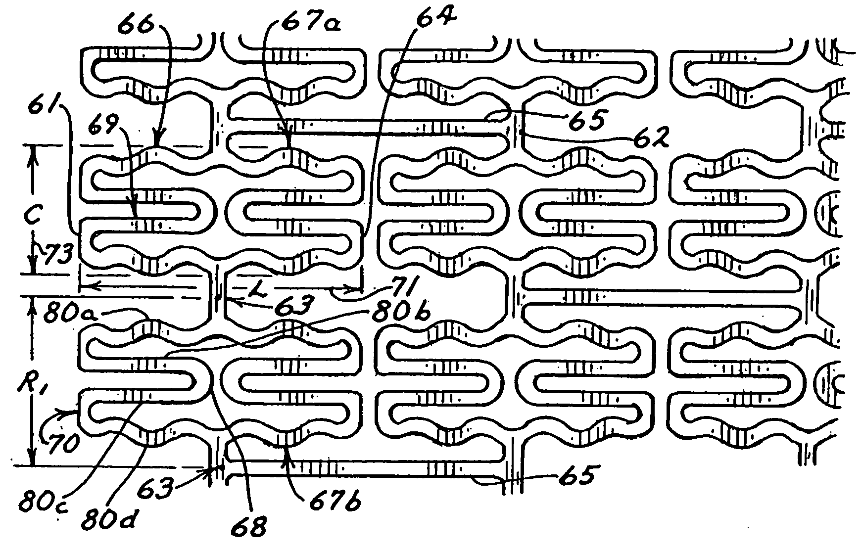
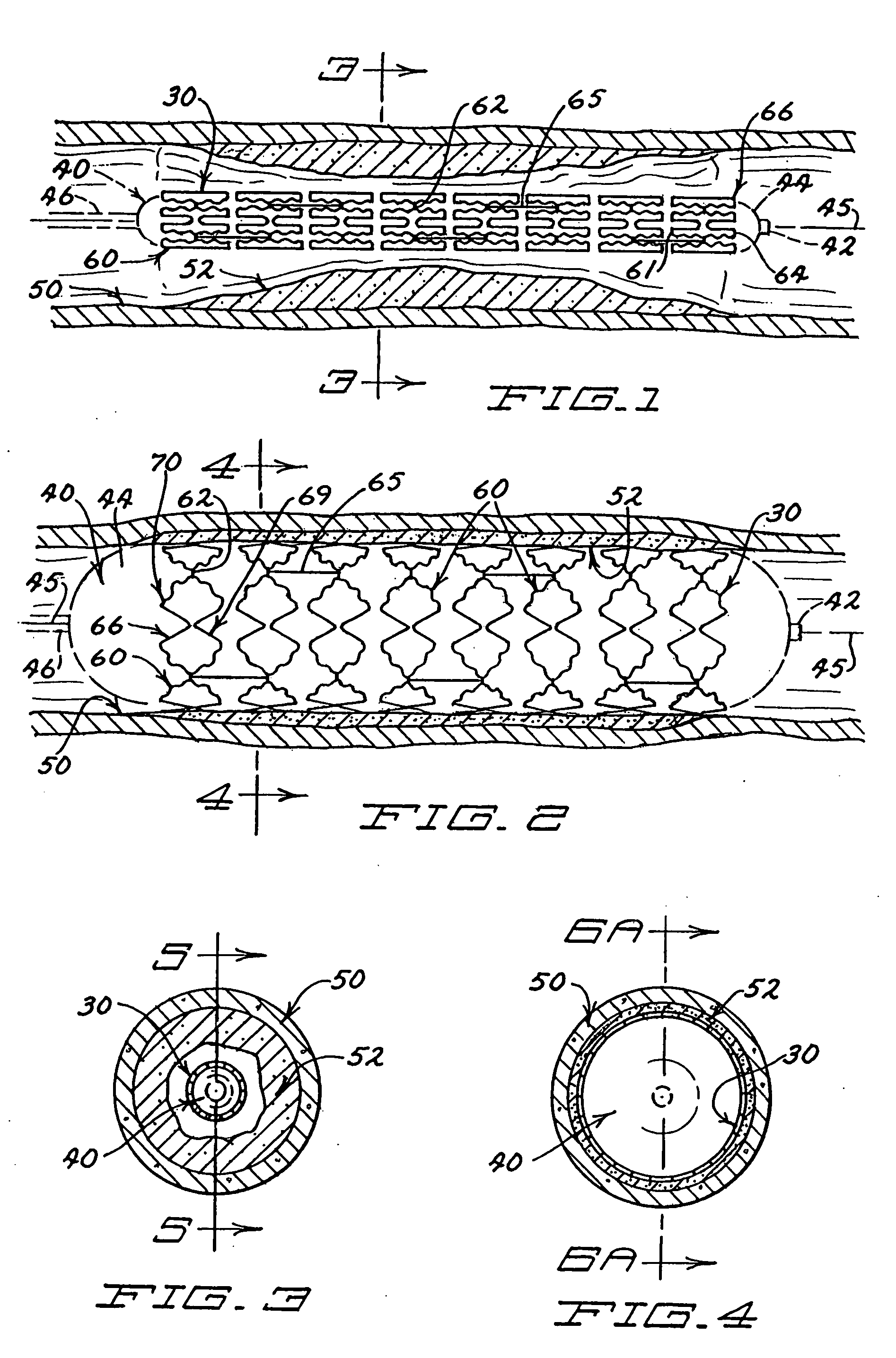
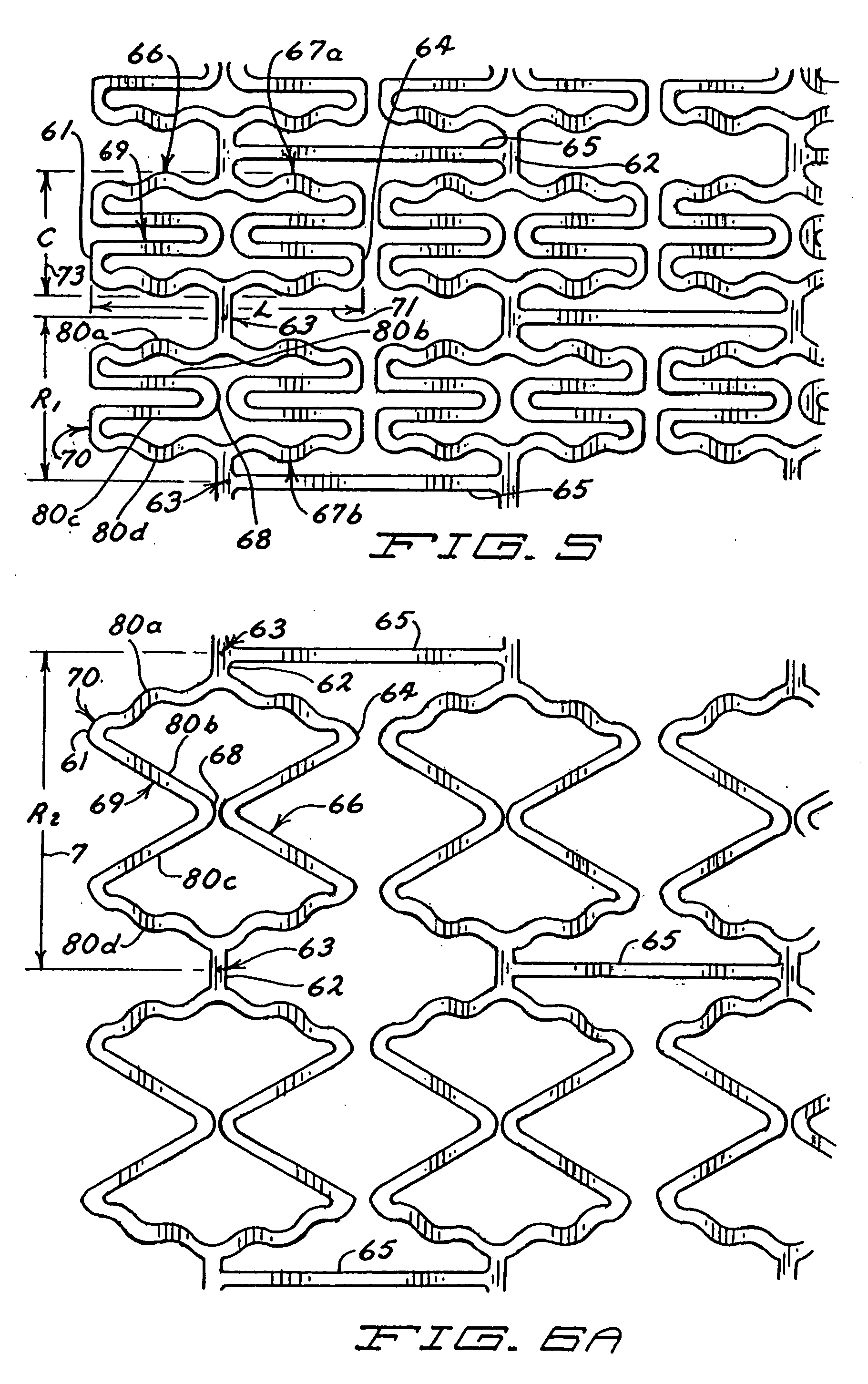
[0051] Referring now to FIGS. 1-4, an expandable stent 30 of the present invention is schematically presented in FIG. 1. The stent 30 has a proximal end 32 and a distal end 34 and is depicted in FIG. 1 as being temporarily fitted upon or generally coaxial with a balloon catheter 40 (shown in hidden line), having a distal end 42, an expandable balloon 44 and a catheter shaft 46. The stent 30 is also shown closely associated within a portion of an artery 50, which is partially occluded by a stenosis 52.

[0052] As shown schematically in FIG. 2, once the stent 30 is appropriately located in the lumen of the artery 50, preferably spanning the stenosis 52, the stent 30 can be expanded outward radially by inflating the balloon 44 of the balloon catheter 40. Inflation of balloon 44 is accomplished by application of fluid pressure to its interior by the cardiologist, acting at the proximal end (not shown) of catheter 40 in a manner, which is well known in the art. As balloon 44 expands, sten...


PUM


Abstract

Expandable stents are disclosed. The stents have a plurality of rings or modules interconnected in series, with selectable links between the rings to provide for articulation. The preferred stent includes a plurality of modules, each of the modules being radially interconnected to form a ring configured to be expandably interconnected and being interconnected to each other in series by respective interconnection bridges. Each ring including a continuous strand of a material, the continuous strand of material being interconnected end to end so as to generally encompass a radial space within the ring. The strand of material being configured to include a repeating series of interconnected repeating W-shaped strand configurations having a repeating dip, rise, dip, rise, loop, dip, rise, dip, rise, loop patterned configuration. Preferably, the continuous strand of a material has an outer surface including cavities being at least partially filled with compositions containing medicinal agents selected to provide medically desirable effects upon positioning within a patient. Preferably, the continuous strand of a material has a series of narrowings that facilitate the bending of the strand. Alternate rings have at least one and preferably a number of expansion cells. The expansion cells preferably have at least one accordion structure on each side of the cell, which allows for significant expansion. The material of the respective stents being deformable such that each ring can be deformed from a first configuration wherein each ring has a first circumference and, in certain embodiments, each expansion cell has a first radial length, to a second configuration wherein each ring has a second circumference greater than the first circumference. Methods of producing the devices are also disclosed, including various etching methods.

Description

CROSS REFERENCE TO RELATED APPLICATIONS [0001] The present application is a Continuation-In-Part Application of U.S. patent application Ser. No. 09 / 379,163, filed Aug. 23, 1999, entitled EXPANDABLE STENT HAVING A PLURALITY OF EXPANSION CELL MODULES, which is a Continuation-In-Part Application of U.S. patent application Ser. No. 08 / 810,819, filed Mar. 5, 1997, entitled EXPANDABLE AND SELF-EXPANDING STENTS AND METHODS OF MAKING AND USING THE SAME.BACKGROUND OF THE INVENTION [0002] The present invention relates to stents and, most preferably, to stents that can be expanded, for example, by expanding an internally positioned balloon. [0003] Under normal circumstances, the heart functions as a pump to perfuse blood throughout the body through arteries. The arteries of some patients are subject to stenosis, a localized partial blockage, which narrows the passageway and interferes with normal blood flow. This condition is termed atherosclerotic coronary artery disease. It is a leading caus...

Claims


Application Information

Patent Timeline
IPC IPC(8): A61F2/00A61F2/06A61F2/84A61F2/90
CPCA61F2/07A61F2/91A61F2/915A61F2/958A61F2002/91508A61F2250/0098A61F2002/91533A61F2002/9155A61F2002/91558A61F2002/91566A61F2002/91516
Inventor DAS, GLADWIN S.
Owner STENT TECH
Learn More