
Cryogenic Probe for Treating Enlarged Volume of Tissue

a cryogenic probe and tissue technology, applied in the field of cryogenic probes, can solve the problems that the background art does not teach or suggest a narrow cryogenic probe, and achieve the effects of large volume of tissue, significant enlargement, and increased effective diameter of cryotips

Active Publication Date: 2008-02-07
ICECURE MEDICAL
View PDF13 Cites 5 Cited by
  • Summary
  • Abstract
  • Description
  • Claims
  • Application Information

AI Technical Summary

Benefits of technology

[0010] The background art does not teach or suggest a cryoprobe or cryocatheter which allows an ice ball formed around the cryotip to be enlarged significantly, without inflating the cryotip and without substantial increase of the effective diameter of the cryotip itself. Also the background art does not teach or suggest a narrow cryogenic probe that can treat a relatively large volume of tissue.
[0011] The present invention overcomes these drawbacks of the background art by providing a narrow cryogenic probe that can treat a relatively large volume of tissue, optionally and preferably by permitting an ice ball having a diameter larger that of the cryotip to be formed around the cryotip, by permitting an increase of the effective diameter of the treatment area after the cryotip enters the tissue to be treated, through protrusion and displacement of at least one and preferably a plurality of needles.

Problems solved by technology

Also the background art does not teach or suggest a narrow cryogenic probe that can treat a relatively large volume of tissue.

Method used


Image

  • Cryogenic Probe for Treating Enlarged Volume of Tissue
  • Cryogenic Probe for Treating Enlarged Volume of Tissue
  • Cryogenic Probe for Treating Enlarged Volume of Tissue

Examples


first embodiment

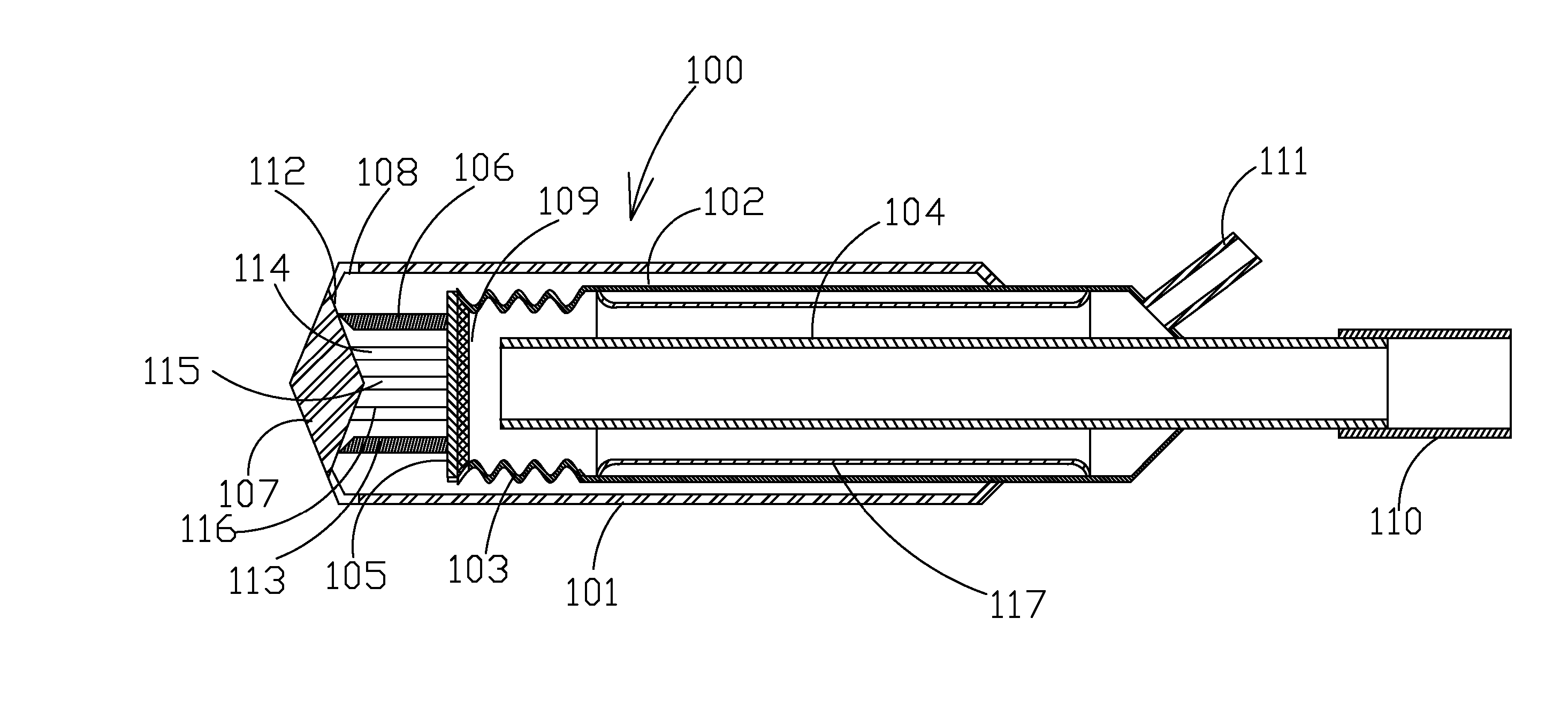
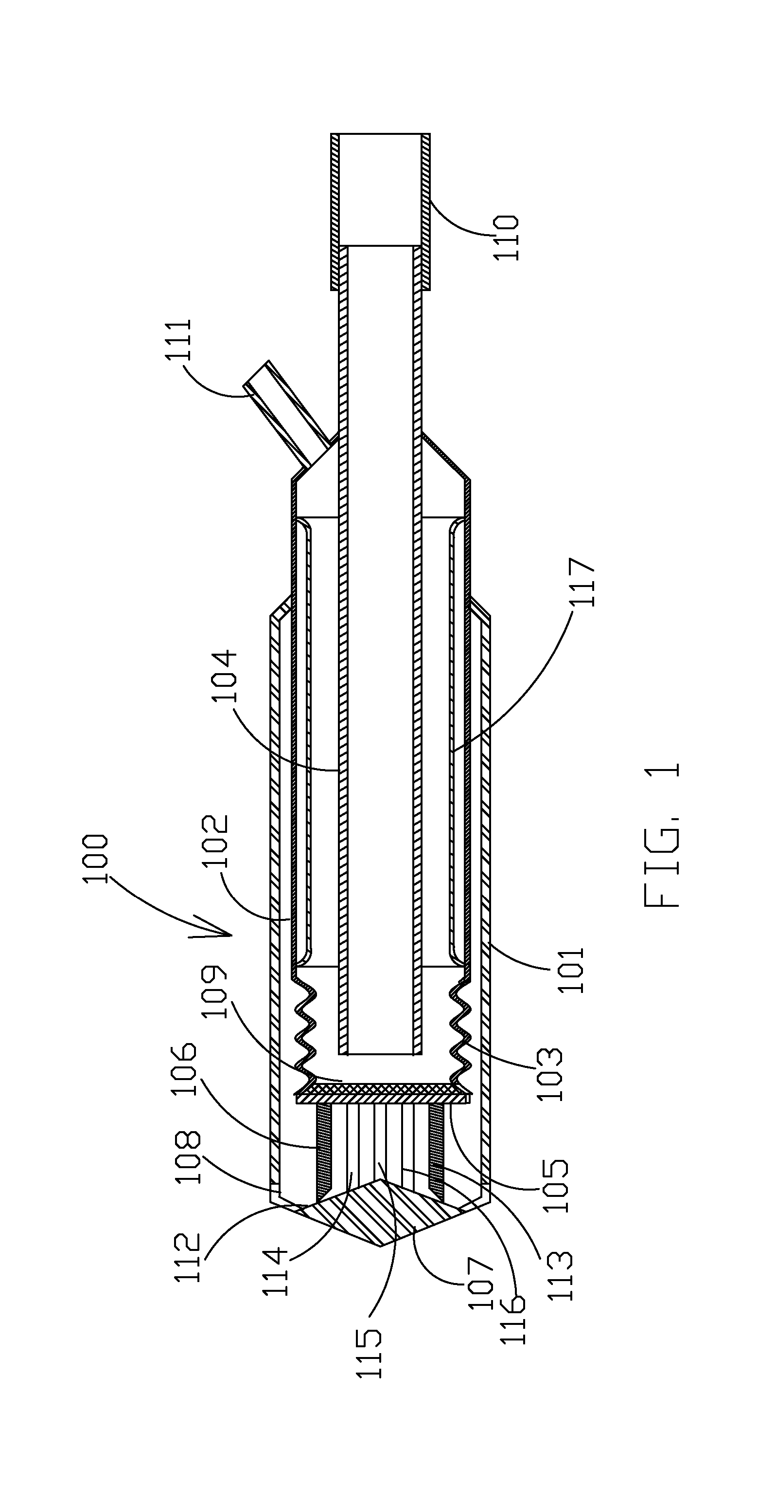
[0028] With reference toFIG. 1, a cryogenic probe 100 in accordance with the present invention is shown. The cryogenic probe 100 is coupled to a cryogenic freezing system (not shown) via connector 110 that serves as an inlet for a cryogenic medium, optionally a cryogenic fluid. Connector 110 is preferably connected to an inner lumen 104 such that a cryogen entering through connector 110 is conveyed down inner lumen 104.

[0029] The cryogenic probe 100 preferably includes an intermediate lumen 102, such that inner lumen 104 is preferably located at least partially within intermediate lumen 102. Intermediate lumen 102 preferably terminates in an expandable element 103, which is optionally and more preferably in the form of bellows. Expandable element 103 is preferably sealed at the distal edge thereof by a face plane 105 to the outer side of which a needle array 106 is appended, such that needle array points forwards, parallel to axis of the intermediate lumen. Face plane 105 may option...

second embodiment

[0039] Referring now to FIG. 3, in a second embodiment, mutatis mutandis, the cryogenic probe 300 may additionally include an additional extending needle 309 for being extended through a central hole 308 in the deflecting member 307.

[0040] Internal surface of face plane 305 optionally and preferably features a porous coating 311 with open porosity for absorbing the cryogenic medium, thereby improving heat transfer to face plane 305. A connector 312 permits cryogenic medium to enter an inner lumen 304, as for connector 110 and inner lumen 104 of FIG. 1. An outlet connection 313 is provided, similar to outlet connection 111 of FIG. 1. An external lumen 301 is provided, similar to external lumen 101 of FIG. 1. An expandable element 303 is provided, similar to expandable element 103 of FIG. 1.

[0041] Central needle 309 preferably protrudes from this central opening 308 upon an increase of pressure in the internal space of the intervening lumen 302. In addition, the distal section of the...

third embodiment

[0042] Referring to FIG. 4, in a third embodiment, mutatis mutandis, the flexible needle(s) 407 of probe 400 are preferably sealed hollow needle(s) having closed proximal end(s) and closed distal end(s), with the needles preferably serving as heat pipe(s), i.e. they are filled with a cryogen, such that movement of cryogen in the internal space of the needle allows effective heat transfer from the proximal section of each needle to its distal section. The inner walls of needles 407 are preferably provided with a porous coating 411 with open porosity. In case of a liquid cryogen, the cryogen may also comprise a gaseous phase or alternatively may only feature a gaseous phase after boiling of the liquid. A face plane 408 is also preferably provided with a porous coating 412 as previously described with regard to FIG. 3 (face plane 305 and porous coating 311). A connector 405 and an outlet connection 406 are provided as previously described with regard to FIGS. 1-3 (see for example conne...


PUM


Abstract

A cryoprobe for surgical and other treatments. The cryoprobe comprises an expandable section that performs displacement of a distal cryotip forwards when there is elevation of the operation pressure in the interior of the cryoprobe. Needle-wise metal elements are installed on the external side of the cryotip. These needle-wise elements are deflecting outwards by a deflecting member fastened on the distal edge of an external shaft of the cryoprobe. This allows a significant enlargement of the frozen volume of the treated tissue with the same operation temperature and the outer diameter of the cryoprobe. In another embodiment, the needle elements are formed in a displaceable metal sheath and a distal section of a cryotip and / or special protrusions on this distal section act as the deflecting member.

Description

FIELD OF THE INVENTION [0001] The present invention is directed to providing a cryogenic probe for medical applications, such as surgery. BACKGROUND OF THE INVENTION [0002] Cryogenic technology provides cooling to very low temperatures. It is widely used in medicine, and particularly in surgery. Freezing tissue can kill its cells, and this makes cryosurgery particularly useful for treating cancerous growths. A cryogenic-probe may be used to kill the cells of malignant cysts in mammary tissue. The cryoprobe is required to have a small diameter to cause minimal damage and trauma to the body tissue in its passage through body tissue. [0003] Typically, the site requiring treatment is significantly larger than the diameter of the cryoprobe and is all too frequently wider than the effectively frozen volume of tissue that is treatable by a single probe insertion. Use of multiple probes causes additional trauma and discomfort. Indeed, it will be appreciated that resorting to such procedures...

Claims


Application Information

Patent Timeline
Patent Type & Authority Applications(United States)
IPC IPC(8): A61B18/02
CPCA61B2018/0268A61B18/02
Inventor TOUBIA, DIDIERLEVIN, ALEXANDERKAGANOVICH, MIRON
Owner ICECURE MEDICAL
Learn More