

Imaging lens and imaging unit
a technology of imaging unit and lens, which is applied in the field of imaging lens, can solve the problems of difficult to reduce the height, difficult to reduce the principal point distance, and the principal point distance tends to increas
- Summary
- Abstract
- Description
- Claims
- Application Information
AI Technical Summary
Benefits of technology
Problems solved by technology
Method used
Image

Examples
numerical example 1
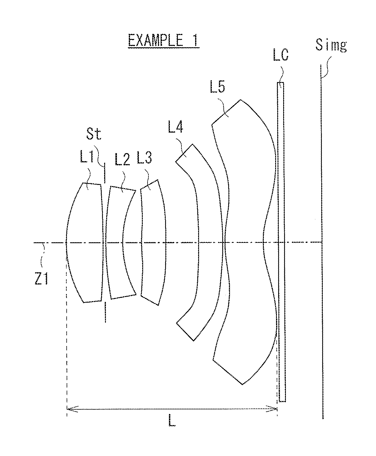
[0056]Table 1 and Table 2 each show specific lens data corresponding to the imaging lens according to the first configuration example illustrated in FIG. 1. In particular, Table 1 shows basic lens data thereof, and Table 2 shows data related to the aspherical surfaces thereof.
[0057]In Tables 1 and 2, the surface numbers are attached so that the numbers are gradually increased toward the image side where a surface of a most-object-sided constituent element is set as the 1st surface. As the basic lens data in Table 1, there are shown a value of a paraxial curvature radius (mm) of each of the surfaces, a value of a spacing (mm) along the optical axis between adjacent surfaces, a value of a refractive index at a d-line (having a wavelength of 587.6 nm) of a material (medium) configuring the lens, and a value of an Abbe number thereof. A surface having a curvature radius shown as “INFINITY” is a planar surface.
[0058]It is to be noted that data is shown in similar forms also in tables for...
numerical example 2
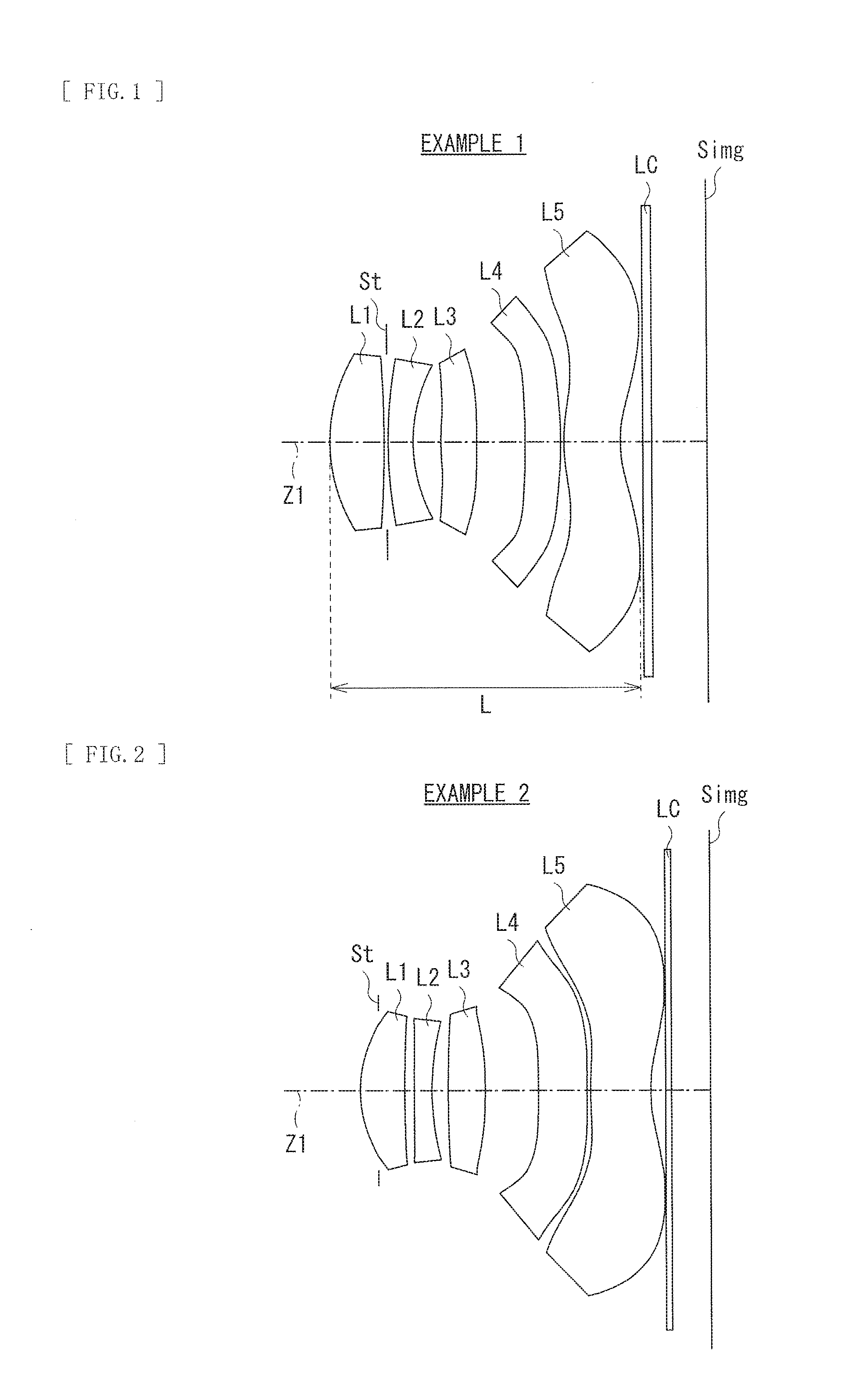
[0060]Table 3 and Table 4 each show specific lens data corresponding to the imaging lens according to the second configuration example illustrated in FIG. 2. In particular, Table 3 shows basic lens data thereof, and Table 4 shows data related to the aspherical surfaces thereof.
[0061]In the second configuration example, the aperture stop St is provided on the object side of the first lens L1. Also, each of the lenses of the first lens L1 to the fifth lens L5 is configured of a plastic lens. The optical member LC such as a cover glass for protecting the imaging device or various optical filters is provided between the fifth lens L5 and the image plane Simg.
TABLE 3Example 2ElementSurfaceCurvatureRefractiveAbbenumbernumberradiusSpacingindex (d)number1 (Stop)—−0.3L121.91690.7231.534656313.71270.145L249.33150.3001.6349323.952.87520.260L365.96890.6011.5346567−9.79100.873L48−8.89290.8001.6349323.99−15.53940.047L5104.34210.9841.534656111.96340.235LC12INFINITY0.111.518264.113INFINITY0.63
TABLE...
numerical example 3
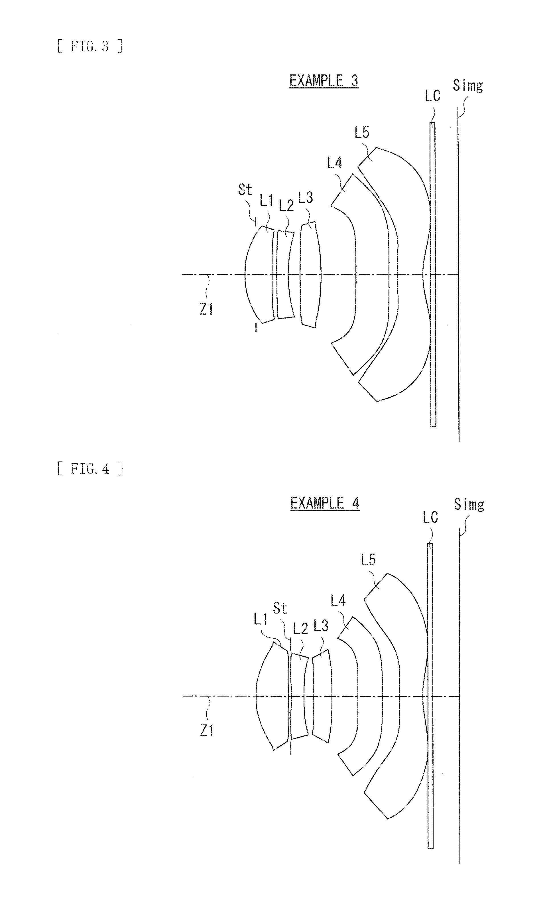
[0062]Table 5 and Table 6 each show specific lens data corresponding to the imaging lens according to the third configuration example illustrated in FIG. 3. In particular, Table 5 shows basic lens data thereof, and Table 6 shows data related to the aspherical surfaces thereof.
[0063]In the third configuration example, the aperture stop St is provided on the object side of the first lens L1. Also, each of the lenses of the first lens L1 to the fifth lens L5 is configured of a plastic lens. The optical member LC such as a cover glass for protecting the imaging device or various optical filters is provided between the fifth lens L5 and the image plane Simg.
TABLE 5Example 3ElementSurfaceCurvatureRefractiveAbbenumbernumberradiusSpacingindex (d)number1 (Stop)—−0.3L121.92570.7171.534656312.24750.131L248.36240.3091.634923.952.86860.327L367.67750.5461.5346567−9.97620.963L48−432.24010.8741.634923.99−500.00000.212L5103.56840.6691.534656111.65610.218LC12INFINITY0.111.518264.113INFINITY0.63
TABLE ...
PUM
 Abstract
Description
Claims
Application Information