Motion transmitting device, mold assembly and machines

Active Publication Date: 2017-10-05
TECHNOCRATS CORP
View PDF4 Cites 4 Cited by
  • Summary
  • Abstract
  • Description
  • Claims
  • Application Information

AI Technical Summary

Benefits of technology

The present invention provides a motion transmitting device that can be easily downsized and weight reduced through a simple construction. The device includes a slider and a connecting body that move along guides and have contact surfaces that can slide with each other. The angle of the guides and a spring can adjust the amount of displacement and speed of displacement of the output end relative to the input end. This allows for a compact and lightweight motion transmitting device to be developed.

Problems solved by technology

On the other hand, it is not easy to achieve downsizing and weight saving of a motion transmitting device, since the motion transmitting device is constituted of numerous component parts, as it is apparent, for example, in a speed reducer.
In particular, the larger the deviation between the input end and the output end is, for example, due to driving the input end and the output end with different speeds, or due to making the input end and the output end have different direction, structure of the motion transmission mechanism is more complicated, making it difficult to reduce size and weight of the motion transmission mechanism.

Method used


Image

  • Motion transmitting device, mold assembly and machines
  • Motion transmitting device, mold assembly and machines
  • Motion transmitting device, mold assembly and machines

Examples


first embodiment

[0112]The connecting body disposed between the two sliders so as to act thereon as described hereinabove may have a flat plate shape. Also, the connecting body may have a rod-like shape. This equally applies to the connecting body 51 in the motion transmitting device 1 designed according to the In summary, it is satisfactory if the connecting body is adapted to be pushed by the slider in contact with one end thereof so as to move along a connecting body guide so that the slider then in contact with the other end may be pushed by the connecting body. While the connecting body of a flat plate shape is shown in this embodiment, the slider may also have a flat plate shape or a rod-like shape as shown in the below described embodiment.

[0113]The slider and the connecting body may respectively have an appropriate shape depending on the application, the magnitude of the amount of motion to be transmitted, or the like. Since a rod-like shape or a flat plate shape can be used for the slider ...

third embodiment

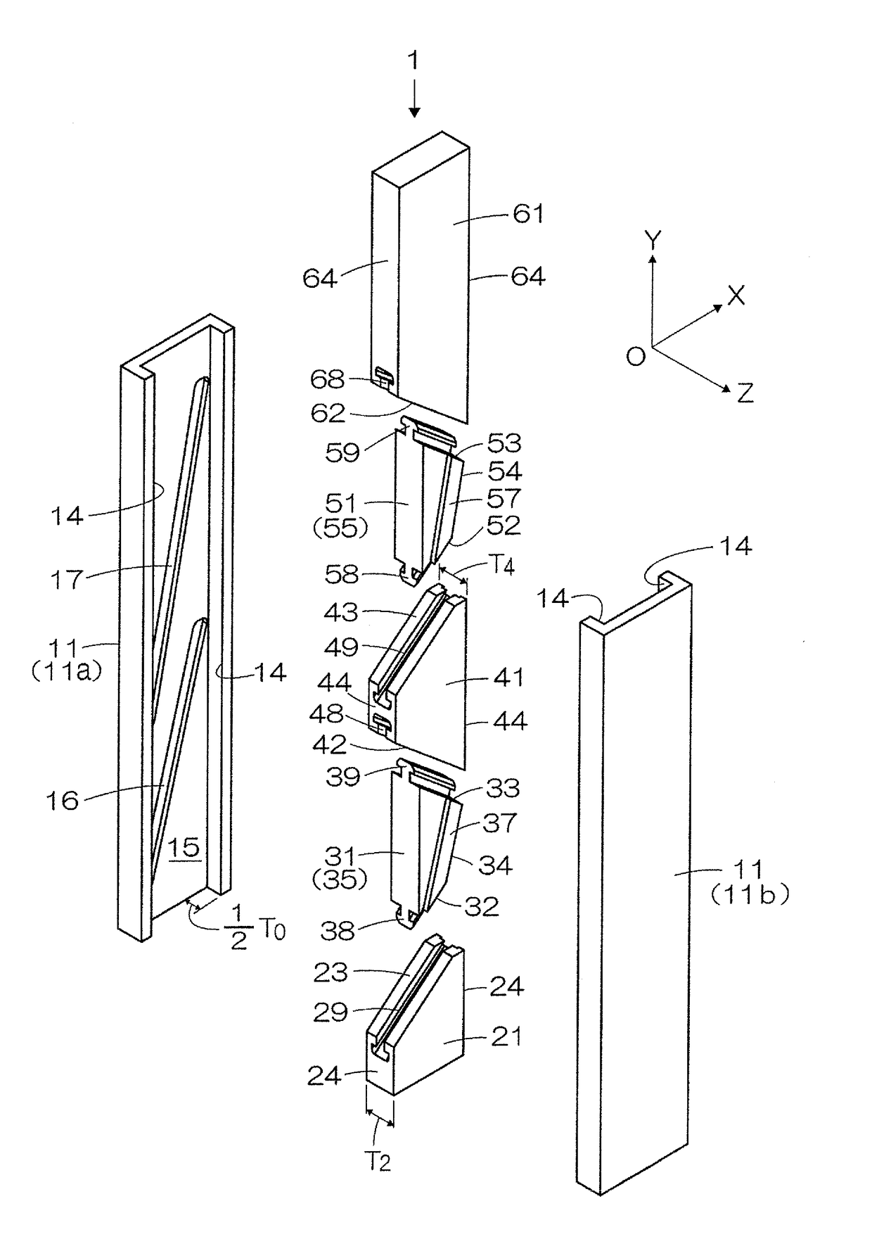
[0122]In the holder 11 (12) employed in any of the motion transmitting devices 1, 2, 3, 4 and 5 wall surfaces are provided in all lengthwise directions. Since portions of the holder 11 (12) which guides the slider 21 (26) are the opposite side surfaces, a groove 20 may be provided in each of the opposite side surfaces, and a projection 22, which slidably engages in the groove 20, may be provided in each of the opposite side surfaces 24 of the slider 21 (26), leaving a ceiling surface and a bottom surface open. This equally applies to the slider 61.

[0123]FIGS. 11A and 11B are diagrams used to explain the operation of the motion transmitting device 6 according to a fourth embodiment of the present invention. FIG. 11A represents a state before being pushed and FIG. 11B represents a state after the slider 21 has been pushed. Structures identical with those employed in any one of the motion transmitting devices 1, 2 and 3 according to the first embodiment shown in and described with ref...

fourth embodiment

[0133]The connecting body 78 has a thickness that is double the connecting body 73 employed in the Viewing the connecting body 78 while dividing the connecting body 78 to two portions in the thicknesswise direction, the connecting body 78 has a structure similar to that of the connecting body 73 in one side (upper side in FIG. 12 C), whereas the other side (lower side in FIG. 12C) has a rectangular plate-shaped member 81 that is elongated to cover a slantwise surface 80. This plate-shaped member 81 will serve as a second output end. A portion of the connecting body 78 adjacent the slantwise surface 79 represents an end surface that is the same as up and down and represents a thickness that is double the slantwise surface 74 of the connecting body 73.

[0134]The interior space of the holder 72 has a height T0 that is identical with those of the sliders 21, 41 and 61 and the connecting body 51, but only a portion of the connecting body 78 has a height that is twice the T0. As shown in ...


PUM

PropertyMeasurementUnit
Angleaaaaaaaaaa
Angleaaaaaaaaaa
Speedaaaaaaaaaa

Abstract

A motion transmitting device comprising: a slider movable along a slider guide; and a connecting body movable along a connecting body guide, wherein the slider and the connecting body are disposed in contact with each other, each of the slider and the connecting body has a contact surface that is slidable, and the amount of displacement and / or the speed of displacement of an output end relative to an input end can be reduced or can be made equal to each other or increased through setting of the angle of a center axis line of the slider guide about a center axis line of the connecting body guide and / or the inclination angle of the contact surface.

Description

CROSS REFERENCE TO THE RELATED APPLICATION[0001]This application is based on and claims Convention priority to Japanese patent application No. 2016-065928, filed Mar. 29, 2016, the entire disclosure of which is herein incorporated by reference as a part of this application.BACKGROUND OF THE INVENTIONField of the Invention[0002]The present invention relates to a motion transmitting device that can be utilized in the form of an equipment incorporated in automotive vehicles, machine tools, transport devices, robots or the like, and also to mold assemblies and various kinds of machines utilizing such motion transmitting device.Description of Related Art[0003]As is well known to those skilled in the art, an actuator and a motion transmitting device (power transmitting device) have been developed in various forms and are utilized in forms of an equipment incorporated in an automotive vehicle, a machine tool, a transport device or the like. The motion transmitting mechanism makes use of a ...

Claims


Application Information

Patent Timeline
IPC IPC(8): F16H25/18
CPCF16H25/183B29C33/20F16H37/02B29C45/332B29C45/44F16H21/04F16H21/10B29C33/442B29C2045/445
Inventor SORIMOTO, MASANORI
Owner TECHNOCRATS CORP
Why Eureka
Try Eureka