
Hub of a wind turbine

Active Publication Date: 2014-12-04
IMO HOLDING GMBH
View PDF11 Cites 0 Cited by
  • Summary
  • Abstract
  • Description
  • Claims
  • Application Information

AI Technical Summary

Benefits of technology

The invention allows for the wind turbine's rotor blades to be rotated relative to each other using large rolling bearings with differently oriented axes of rotation. These bearings can be united with each other by processing or shaping a common base body, such as the hub body of the wind turbine. This design eliminates the need for a spider or planet carrier, resulting in a simplified arrangement and weight savings.

Problems solved by technology

Even such screw connections do not make for a completely rigid connection, of the kind obtained by welding, for example, and further require thick rings or plates on the mating structure to produce the necessary rigidity.

Method used


Image

  • Hub of a wind turbine
  • Hub of a wind turbine
  • Hub of a wind turbine

Examples


Embodiment Construction

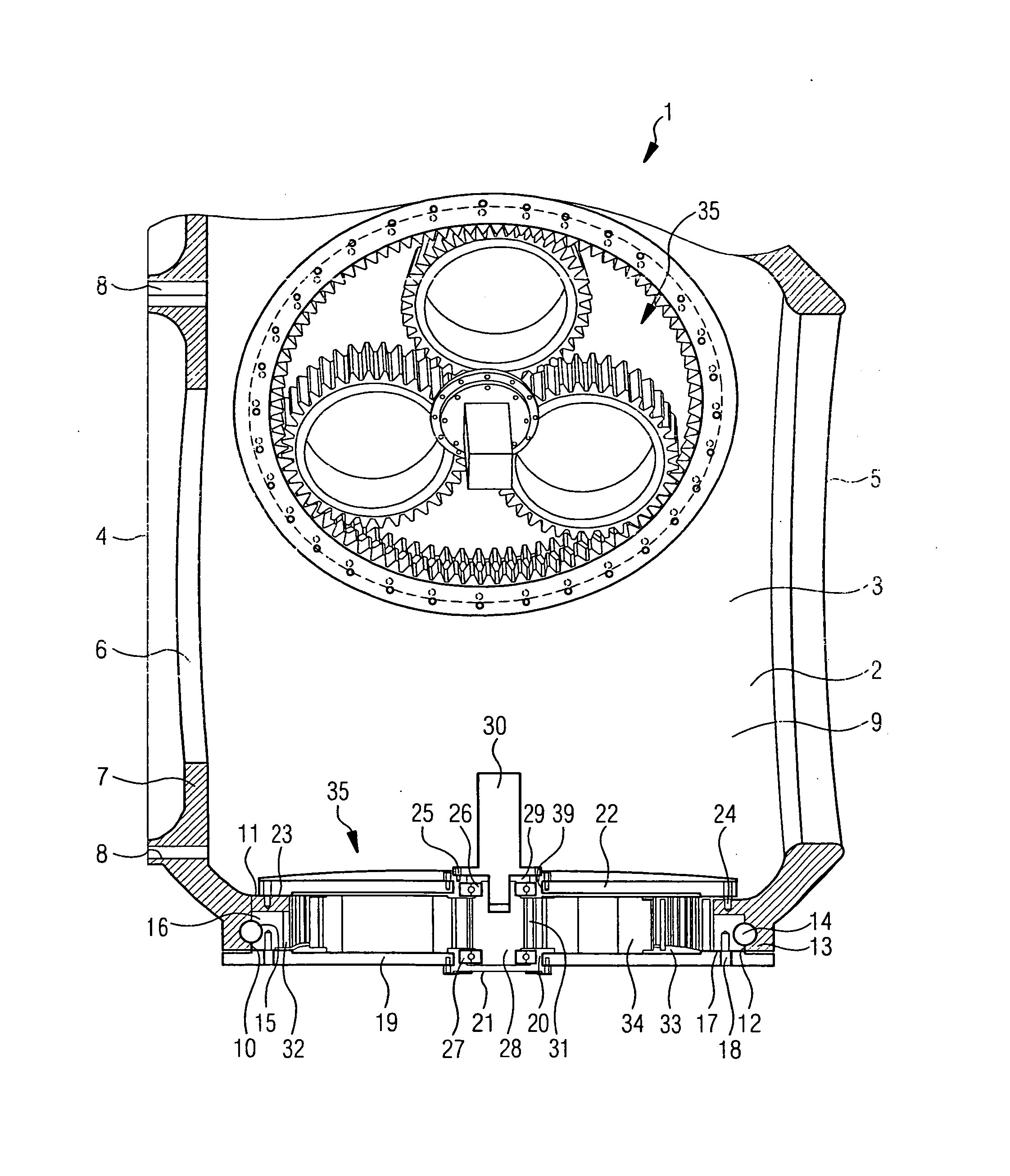
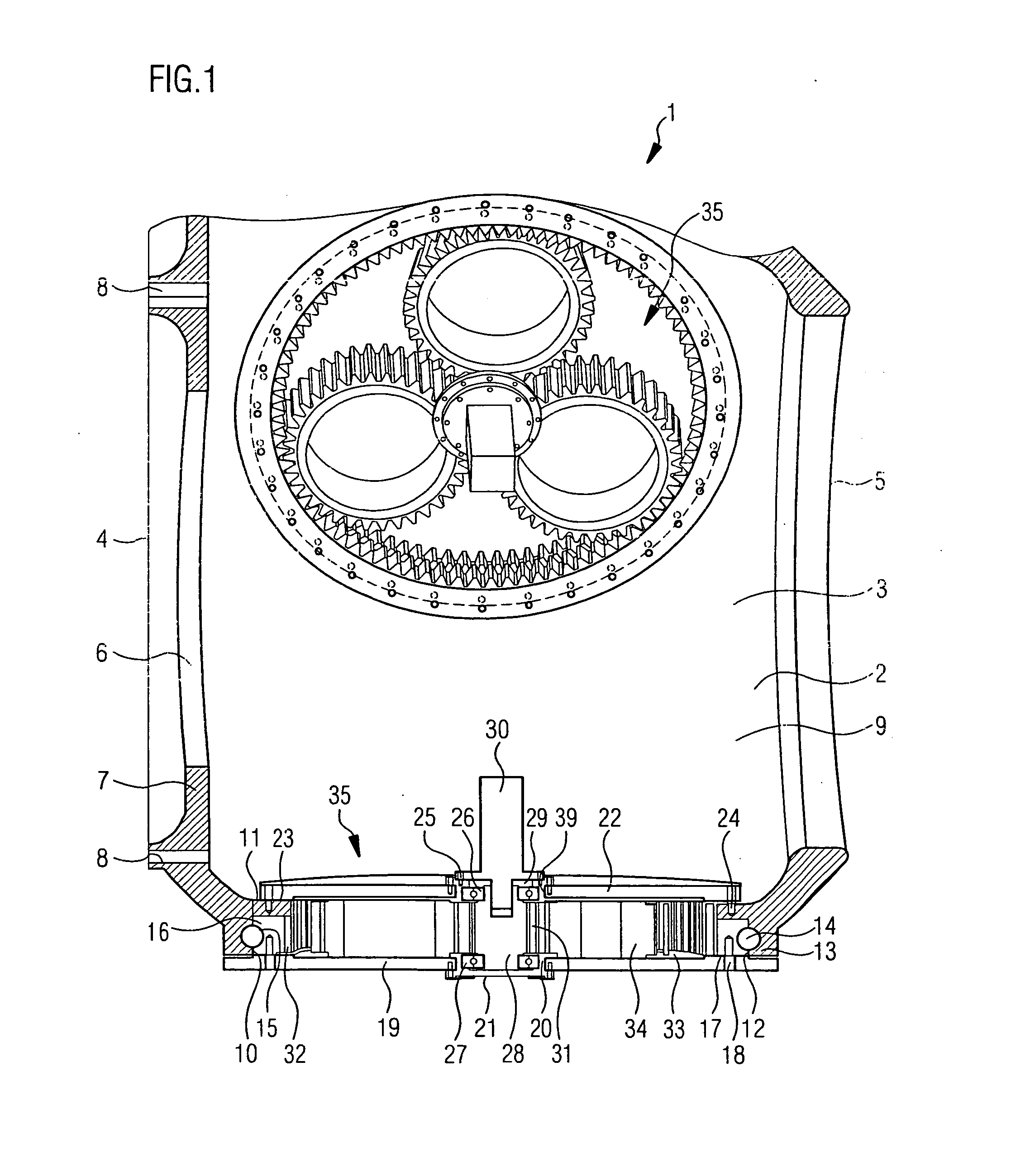
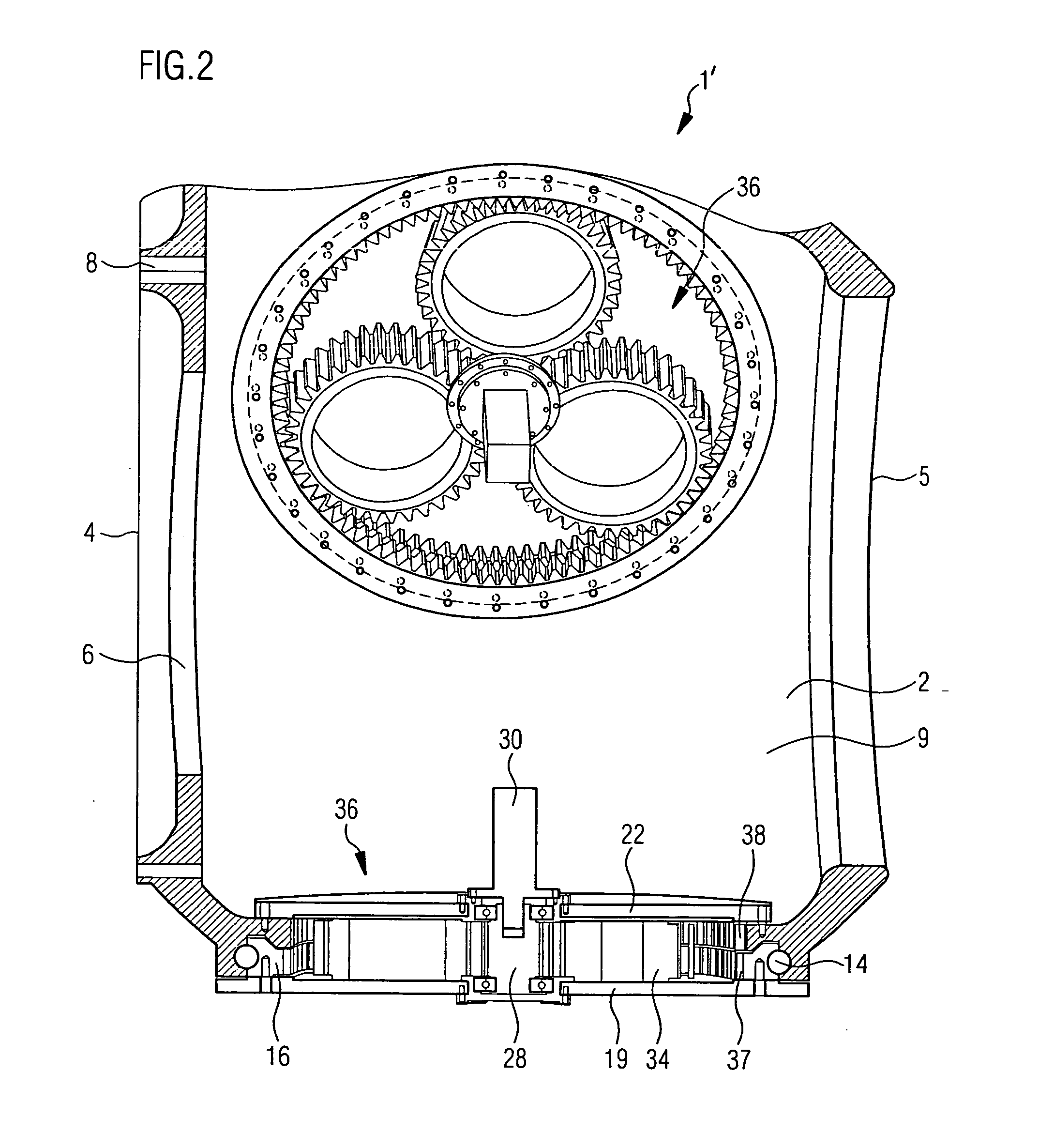
[0035]FIG. 1 depicts a hub 1 of a wind turbine, as an example of a device according to the invention for adjusting a plurality of elements relative to one another. This broken-away sectional representation reveals the hub body 2, which has approximately the shape of a ring with multiple openings therethrough. This ring has, for example, a jacket 3 with an approximately cylindrical structure, preferably tapering to both end faces 4, 5.

[0036]On the end face 4 proximate the nacelle, the end-face opening 6 there is narrowed further by a circumferential, inwardly projecting flange 7. Provided therein is a plurality of fastening bores 8 to effect attachment to an output-side rotation device, for example a main bearing of the wind turbine, a gearbox input or a generator.

[0037]The end face 5 remote from the nacelle, on the other hand, can be closed off directly or by means of a cowl (not shown), to keep the oncoming wind out of the interior space 9 of the hub 1.

[0038]The jacket 3 of this on...


PUM


Abstract

A wind turbine hub having both blades mounted thereon by means of blade bearings adjustable about the longitudinal axes thereof. The turbine includes means for effecting multi-axes adjustments of a plurality of elements relative to one another. The elements are rotatable about bearings having selectively oriented axes of rotation, each bearing comprising two parts rotatable relative to each other.

Description

BACKGROUND OF THE INVENTION[0001]1. Field of the Invention[0002]The invention is directed to a device for the multi-axis adjustment of a plurality of elements relative to one another, wherein the elements are rotatable relative to one another via two or more bearings having differently oriented axes of rotation, and wherein each bearing has two parts that can be rotated relative to each other about their respective axes of rotation, particularly to a hub of a wind turbine having rotor blades that are mounted to the hub by means of blade bearings and can be adjusted about their respective longitudinal axes.[0003]2. Description of the Prior Art[0004]Modern large rolling bearings have diameters above the 2-meter range in many applications, and use cases involving diameters of 5 or even 8 meters are not uncommon nowadays. One example of such an application is modern wind turbines, whose wind wheels are constantly being built larger to increase performance. The larger the diameter of suc...

Claims


Application Information

Patent Timeline
IPC IPC(8): F03D11/00F03D7/04F03D7/02
CPCF03D11/0008F03D7/04F03D7/0224F16C35/04F03D1/0691F05B2260/79F16C19/16F16C33/581F03D80/70F16C2300/14F16C2360/31Y02E10/72B64C11/02F03D1/06F16C19/14F03D80/80B64C11/04
Inventor FRANK, HUBERTUS
Owner IMO HOLDING GMBH
Learn More