Method for manufacturing a composite material connecting rod having reinforced ends

Active Publication Date: 2012-05-03
SAFRAN LANDING SYST
View PDF5 Cites 0 Cited by
  • Summary
  • Abstract
  • Description
  • Claims
  • Application Information

AI Technical Summary

Benefits of technology

[0017]The mandrel performs two functions: it constitutes a support on which the fibers are braided in a suitable shape, and because of its reinforced ends it provides the required impact strength in the regions of the rod where the external forces are introduced.
[0018]The invention thus makes it possible to make a one-piece rod having reinforced ends while using a technique of braid

Problems solved by technology

However, that solution remains limited by the fact that the metal endpieces 12 and 13 are predom

Method used


Image

  • Method for manufacturing a composite material connecting rod having reinforced ends
  • Method for manufacturing a composite material connecting rod having reinforced ends
  • Method for manufacturing a composite material connecting rod having reinforced ends

Examples


Embodiment Construction

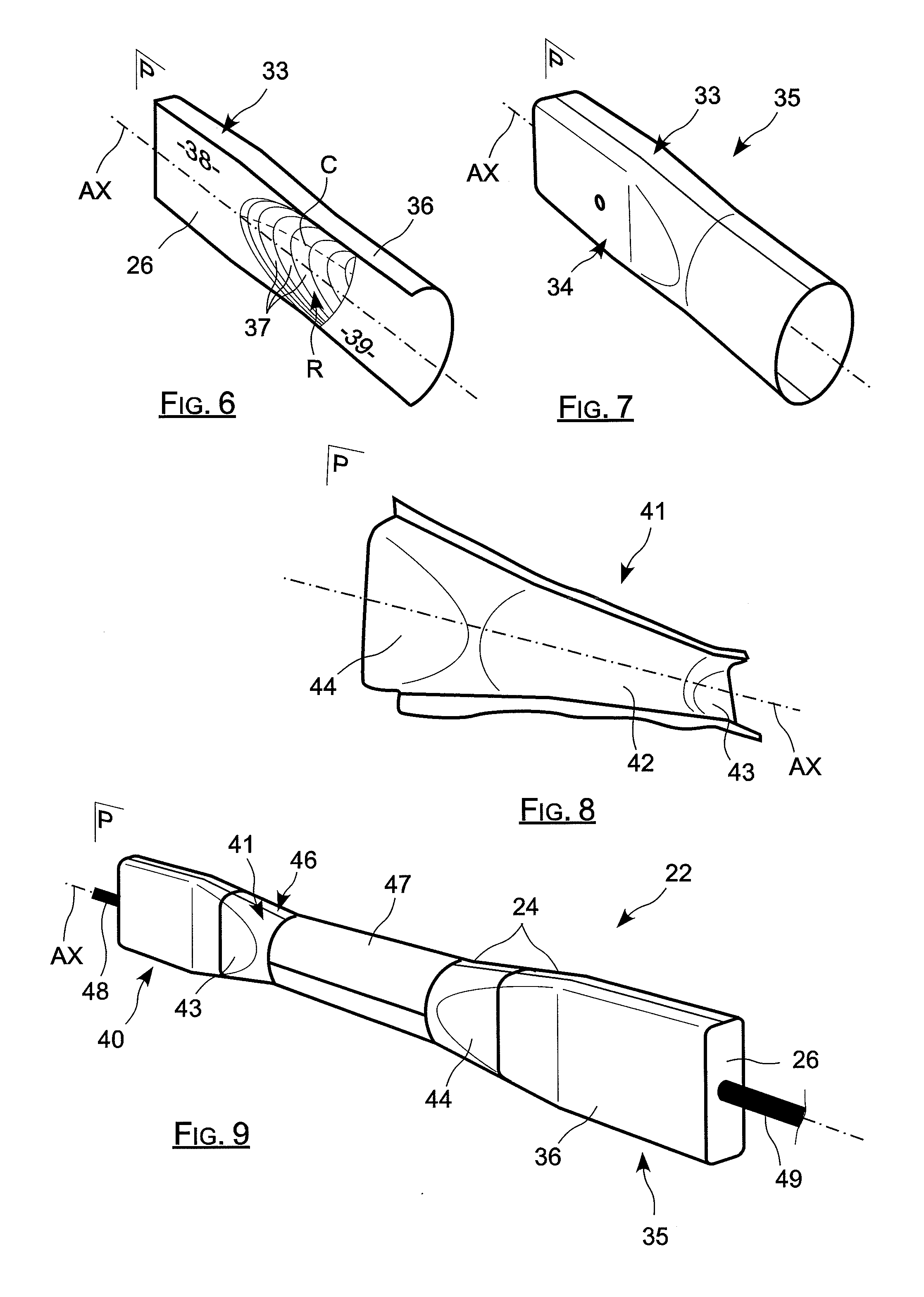
[0038]The idea on which the invention is based is to fabricate a rod out of composite material by braiding fibers around a mandrel having ends, which ends are reinforced in order to increase the mechanical strength of the ends of the rod when considered as a whole.

[0039]The mandrel thus performs two functions: it constitutes a support on which the layers of fibers are braided in order to take up the appropriate geometrical shape, and the solid inserts at its ends provide the extra material needed for providing its lugs with impact strength.

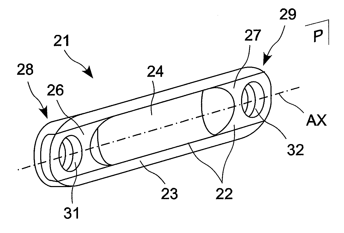
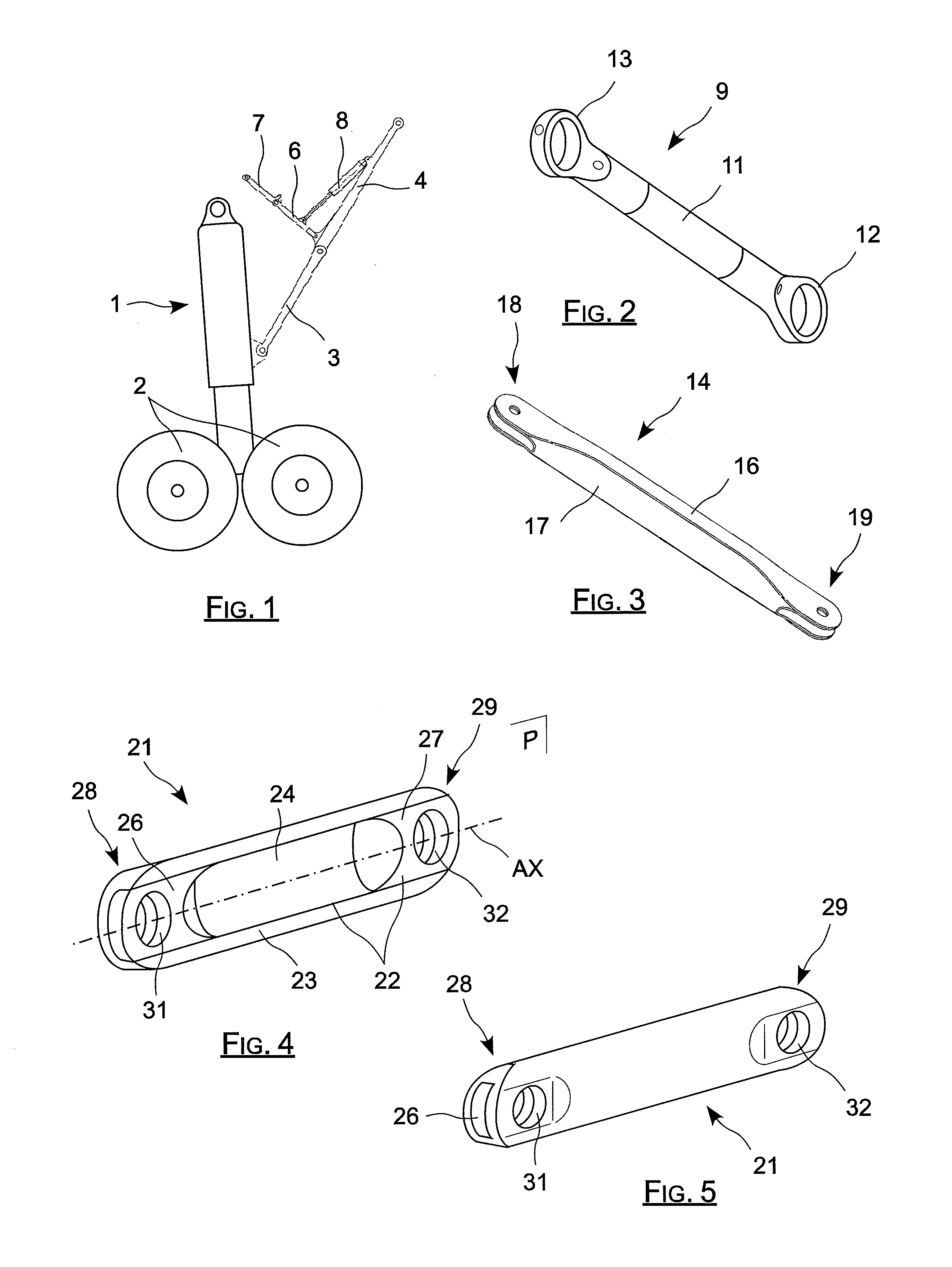
[0040]As can be seen in FIGS. 4 and 5, the rod of the invention, which extends longitudinally along an axis AX, is made from a mandrel 22 of composite material having one or more layers 23 of reinforcing fibers such as carbon fibers braided around the mandrel.

[0041]The mandrel 22 comprises a hollow tubular body 24 forming a sleeve having two inserts 26 and 27 secured thereto, which inserts are engaged in the ends of the tubular hollow body. As can...


PUM

PropertyMeasurementUnit
Cohesionaaaaaaaaaa

Abstract

In the field of aviation, a method of fabricating a composite-material rod. The method comprises a first step of fabricating a mandrel comprising a sleeve of composite material and solid inserts of composite material secured to the ends of said sleeve to constitute a rigid whole. Then, one or more layers of braided fibers are applied around the mandrel by using a fiber-braiding machine. Next, a resin is injected into the layers of braided fibers so as to establish cohesion rigidly bonding the braided fiber layers and at least the ends of the mandrel in order to form a rod body out of composite material having reinforced ends. Finally, respective holes are drilled at each end of the rod body, each hole passing through the layers of braided fibers and also through the corresponding insert.

Description

[0001]The invention relates to a method of fabricating a rod of composite material such as a rod for an aircraft undercarriage side brace.BACKGROUND OF THE INVENTION[0002]As shown in FIG. 1, an undercarriage typically comprises a leg 1 having a top end hinged to an element of the structure of an aircraft and a bottom end carrying a wheel set 2. In addition, a locking system is provided to hold the assembly securely in the deployed position, as shown in FIG. 1.[0003]The locking system comprises a side brace made up of two hinged-together rods 3 and 4, the rod 3 being hinged to the leg and the other rod 4 being hinged to the structure of the aircraft, with a stabilizer member also being provided for holding the two rods 3 and 4 in alignment with each other.[0004]The stabilizer member comprises two arms 6 and 7 that are hinged together, the arm 6 being hinged for example to the hinge connecting together the rods 3 and 4 while the arm 7 is hinged to the structure of the aircraft. A syst...

Claims


Application Information

Patent Timeline
IPC IPC(8): B29C70/24
CPCB29C70/222B29C70/32B29L2031/75B29C70/86B29C70/48
Inventor MASSON, RICHARDDUNLEAVY, PATRICK
Owner SAFRAN LANDING SYST
Why Eureka
Try Eureka