Combined jet-flow control device for helicopter rotor blade and control method of combined jet-flow control device

A combined jet device and helicopter rotor technology, which is applied to rotorcraft, motor vehicles, transportation and packaging, etc., can solve the problems of weak off-design point working conditions, unsatisfactory control effects, increased resistance, etc., and achieve stall suppression Significant effects, avoiding adverse effects, improving work performance and efficiency

Inactive Publication Date: 2016-10-12
NORTHWESTERN POLYTECHNICAL UNIV
View PDF6 Cites 11 Cited by
  • Summary
  • Abstract
  • Description
  • Claims
  • Application Information

AI Technical Summary

Problems solved by technology

The vortex generator is a passive flow control method, which has a certain effect on the separation control of the design point, but has a weak effect on the non-design point working conditions, and will bring the adverse effect of increasing the resistance
Synthetic jet delays the separation of airflow through periodic blowing and suction of openings, which is more effective for certain

Method used


Image

  • Combined jet-flow control device for helicopter rotor blade and control method of combined jet-flow control device
  • Combined jet-flow control device for helicopter rotor blade and control method of combined jet-flow control device
  • Combined jet-flow control device for helicopter rotor blade and control method of combined jet-flow control device

Examples


Embodiment Construction

[0031] In order to make the objects and advantages of the present invention clearer, the present invention will be further described in detail below in conjunction with the examples. It should be understood that the specific embodiments described here are only used to explain the present invention, not to limit the present invention.

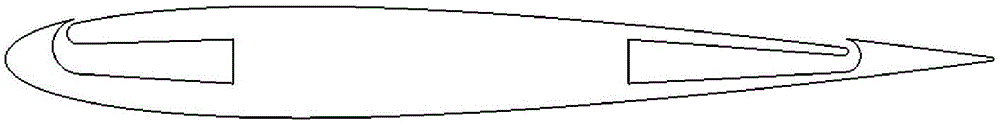
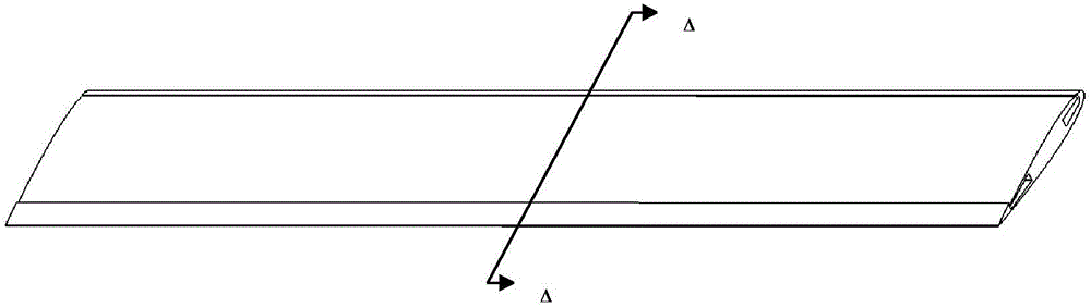
[0032] Such as Figure 2-4 Shown, the embodiment of the present invention provides a kind of combined jet flow control device for helicopter rotor blade, it is characterized in that, it comprises several blades whose geometric shape is NACA0012CFJ airfoil, and each blade is equipped with a combined jet flow device, so The combined jet device is continuously distributed along the span direction of the blade, and the combined jet device includes a high-pressure air chamber and a low-pressure air chamber. The high-pressure air chamber and the low-pressure air chamber are connected to the air pump device inside the helicopter through the airflow pi...


PUM


Abstract

The invention discloses a combined jet-flow control device for a helicopter rotor blade and a control method of the combined jet-flow control device. The combined jet-flow control device comprises a plurality of blades with a geometric shape of NACA0012-CFJ airfoil shape, each blade is provided with a combined jet flow device, the combined jet flow devices are continuously distributed along the unfolding direction of the blade, each combined jet flow device comprises a high pressure air chamber and a low pressure air chamber, the high pressure air chamber is communicated with an air blowing opening at the front edge, the low pressure air chamber is communicated with an air suction opening at the rear edge, and the high pressure air chamber and the low pressure air chamber are communicated with an air pump device inside a helicopter by virtue of an airflow pipeline. A novel-concept initiative flow control technique of combined jet flow is innovatively adopted to suppress the dynamic stalling of the rotor blade, the air is blown from the opening adjacent to the front edge of the upper surface of the airfoil to the rear edge, the air is sucked through the opening adjacent to the rear edge, and the air suction volume and the air blowing volume are ensured to be the same, so that the recycling of the air is realized, and the control method is flexible.

Description

technical field [0001] The invention relates to the technical field of active flow control, in particular to a combined jet flow control device for helicopter rotor blades and a control method thereof. Background technique [0002] Due to its unique flight characteristics, helicopters can take off and land vertically, do not need an airport runway, can hover in the air, and have the ability to fly in any direction, making them irreplaceable by general fixed-wing aircraft in some aspects of military and civilian use. important position. In terms of military use, it has been widely used in ground attack, weapon delivery, logistics support, battlefield rescue, reconnaissance and patrol, command and control, communication, anti-submarine mine clearance, electronic countermeasures, etc. In civil use, it is used in short-distance transportation, medical rescue, disaster relief, emergency rescue, hoisting equipment, geological exploration, forest protection and fire fighting, aeri...

Claims


Application Information

Patent Timeline
IPC IPC(8): B64C27/467B64C27/473B64C27/04
CPCB64C27/04B64C27/467B64C27/473
Inventor 许和勇杨慧强乔晨亮邢世龙叶正寅
Owner NORTHWESTERN POLYTECHNICAL UNIV
Why Eureka
Try Eureka