Method of reducing noise in a rotary electric machine, attachment apparatus for attaching the stator of a rotary electric machine and for implementing the method, and a rotary electric machine provided with such apparatus

a technology of rotary electric machines and attachment apparatus, which is applied in the direction of motors, dynamo-electric machines, wind energy generation, etc., can solve the problems of limited vibrating area of the casing, large acoustic noise and vibration, and limited power of the apparatus

Inactive Publication Date: 2000-08-22
GEC ALSTHOM MOTEURS
View PDF3 Cites 22 Cited by
  • Summary
  • Abstract
  • Description
  • Claims
  • Application Information

AI Technical Summary

Benefits of technology

An object of the present invention is to provide attachment apparatus for attaching the stator to the casing, which apparatus make

Problems solved by technology

One of the reasons for noise and vibration in rotary electric machines results from dynamic forces being transmitted from the stator to the casing in which it is mounted.
The walls of the casing then act as an amplifier, and considerable acoustic noise and vibration ensues.
As a result, the vibrating areas of the casing are limited.
Unfortunately, that apparatus is limited in power because of the effects of the beams bending.
There too, the results as regards reducing acoustic noise and

Method used


Image

  • Method of reducing noise in a rotary electric machine, attachment apparatus for attaching the stator of a rotary electric machine and for implementing the method, and a rotary electric machine provided with such apparatus
  • Method of reducing noise in a rotary electric machine, attachment apparatus for attaching the stator of a rotary electric machine and for implementing the method, and a rotary electric machine provided with such apparatus

Examples


Embodiment Construction

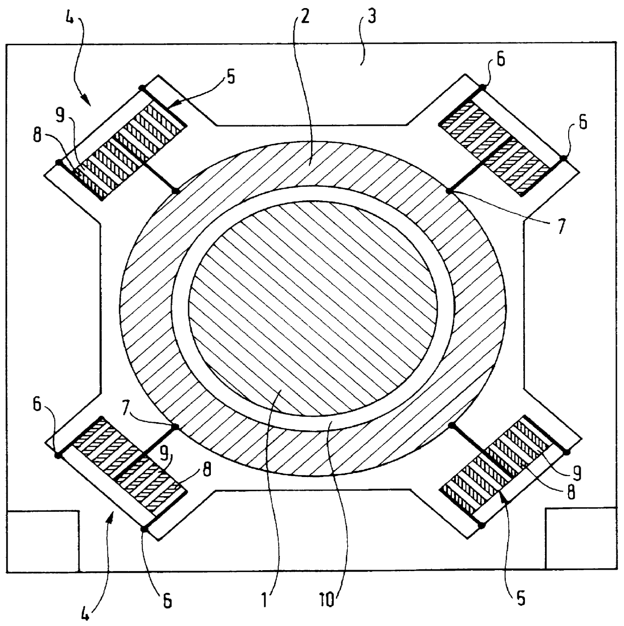
The static forces of the stator are mainly the weight of the stator itself, the static magnetic attraction between the stator and the rotor, the reaction electromagnetic torque (counter-reaction of the stator when the rotor rotates), the inertia forces induced on the stator by the rotary machine being displaced (on-board rotary machine, traction motor, earthquake, etc.).

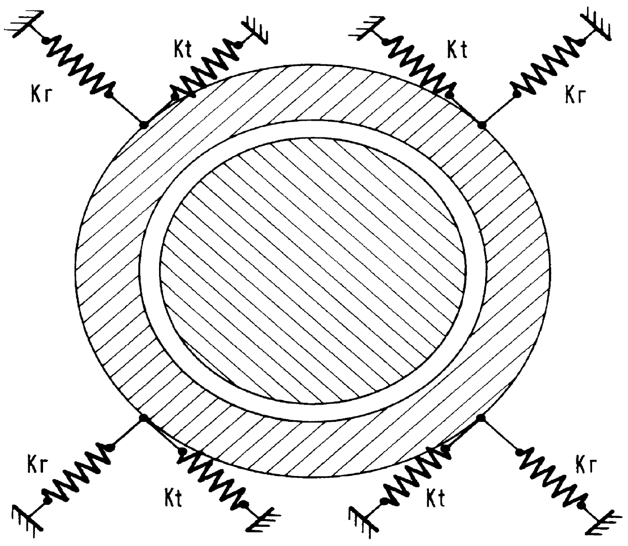
These static forces cause the stator to move off center relative to the rotor. Therefore, in the direction of the resultant of these forces, the stiffness of the attachment apparatus must be high so as to limit eccentricity. This may be achieved with a combination of high tangential stiffnesses at the points of attachment of the stator.

In addition, the dynamic forces of the stator, which forces are the main cause of casing vibration and of noise, give rise to deformations of the radial breathing type or the radial lobe type. It is thus necessary for the stiffness of the attachment apparatus in the radial directions t...


PUM


Abstract

The invention concerns attachment apparatus for a stator of a rotary electric machine, said machine comprising a rotor, a stator coaxial with the rotor, an airgap between the stator and the rotor, and a casing provided with attachment points for attaching the stator; according to the invention, the attachment apparatus comprises attachment elements mounted between the attachment points and the stator; each attachment element having an anisotropic stiffness comprising a tangential component Kt for taking up in part the static forces of the machine, and a radial component Kr for relieving in part the dynamic forces of the stator relative to the casing; the resultant of the tangential components Kt taking up the static forces of the rotary electric machine with an axial displacement or a radial displacement of the stator that is less than or equal to a predetermined value that is less than the airgap; and the resultant of the radial components Kr relieves the dynamic forces of the stator with a predetermined coefficient of transmission to the casing.

Description

One of the reasons for noise and vibration in rotary electric machines results from dynamic forces being transmitted from the stator to the casing in which it is mounted. Such dynamic forces, in particular of electromagnetic origin, appear as vibration starting on the bore radius of the stator. Such vibration is transmitted to the casing via the attachment points at which the stator is attached in the casing. The walls of the casing then act as an amplifier, and considerable acoustic noise and vibration ensues.In one known configuration, the stator is suspended from metal beams themselves associated with the end plates of the rotary machine. As a result, the vibrating areas of the casing are limited. Unfortunately, that apparatus is limited in power because of the effects of the beams bending.In another known configuration, the stator is attached to the casing by attachment systems of the metal shoe type. There too, the results as regards reducing acoustic noise and vibration are in...

Claims


Application Information

Patent Timeline
IPC IPC(8): H02K1/18H02K15/02H02K5/24F03D9/00F16F15/02F03D11/00F16F15/04
CPCF03D9/002F03D11/00H02K1/185H02K15/028H02K5/24Y02E10/722Y02E10/725F03D80/00F03D9/25Y02E10/72Y02P70/50
Inventor DURANTAY, LIONELGALMICHE, CHRISTOPHE
Owner GEC ALSTHOM MOTEURS
Why Eureka
Try Eureka