Laminated core and method for manufacturing the same

a technology of laminated core and manufacturing method, which is applied in the direction of dynamo-electric machines, electrical equipment, magnetic circuit shapes/forms/construction, etc., can solve the problems of uneven thickness of laminated core, affecting the quality of motors, and reducing the efficiency of motors, so as to improve the magnetic efficiency and thus efficiency of the apparatus, reduce vibration and noise, and facilitate quality control

Inactive Publication Date: 2010-04-15
MITSUI HIGH TEC INC
View PDF1 Cites 21 Cited by
  • Summary
  • Abstract
  • Description
  • Claims
  • Application Information

AI Technical Summary

Benefits of technology

[0043]According to the laminated core in the first aspect of and the method in the second aspect of the present invention, the depressed receptacles are formed in a radially outward area of the segment core sheet except for the connecting portions, the depressed receptacles respectively formed on top and bottom sides of the segment core sheet, the depressed receptacle receiving a thickness-direction expanded part formed in the connecting portion in a thickness direction thereof at the bending of the connecting portion. This constitution prevents the thickness-direction expanded parts from forming clearances between the laminated segment core sheets.
[0044]Accordingly, the segment core sheets are closely laminated to improve magnetic efficiency and thus efficiency of the apparatus. In addition, the closely laminated segment core sheets with no clearances reduce vibrations and noises in use of the apparatus. Furthermore, since the laminated core with no clearances has circularity, squareness, and height as previously specified, quality control thereof is facilitated and motor quality is enhanced.
[0045]According to the laminated core in the first aspect of and the method in the second aspect of the present invention, the depressed receptacle has a simple shape if the depressed receptacle has any one of a circular cone shape, a truncated circular cone shape, a four-sided pyramidal shape, a truncated four-sided pyramidal shape, a part-spherical shape, and, when viewed from above, a polygonal shape. In particular, the depressed receptacle with a truncated circular cone shape or a truncated four-sided pyramidal shape has advantages in that its formation is easy and wear of cutting blades is reduced.
[0046]According to the laminated core in the first aspect of the present invention, if the depressed receptacle has a depth of 0.15 times to 0.3 times the thickness (in general, 0.15 mm to 0.3 mm) of the segment core sheet, the depressed receptacle is defined in depth so as to take in the thickness-direction expanded part formed in the connecting portion by the bending thereof, thereby providing the laminated core having a uniform height.
[0047]According to the laminated core in the first aspect of and the method in the second aspect of the present invention, if the depressed receptacle has a through-hole in a center, the excess metal produced by press forming the depressed receptacle move toward the through-hole to make the surface of the segment core sheet free from projections of excess metal (i.e., metal which has escaped from the pressed area).
[0048]According to the laminated core in the first aspect of the present invention, if the through-hole has a volume of 0.7 times to 1.5 times the total volume of the depressed receptacles on the top and bottom sides of the segment core sheet exclusive of the through-hole, it is ensured that the surface of the segment core sheet is free from the projections of excess metal.

Problems solved by technology

The expanded parts create gaps between the laminated segment core sheets, causing the obtained laminated core to have uneven thickness.
The gaps reduce efficiency of the motor or cause vibration therein to negatively affect the motor quality.

Method used


Image

  • Laminated core and method for manufacturing the same
  • Laminated core and method for manufacturing the same
  • Laminated core and method for manufacturing the same

Examples


first embodiment

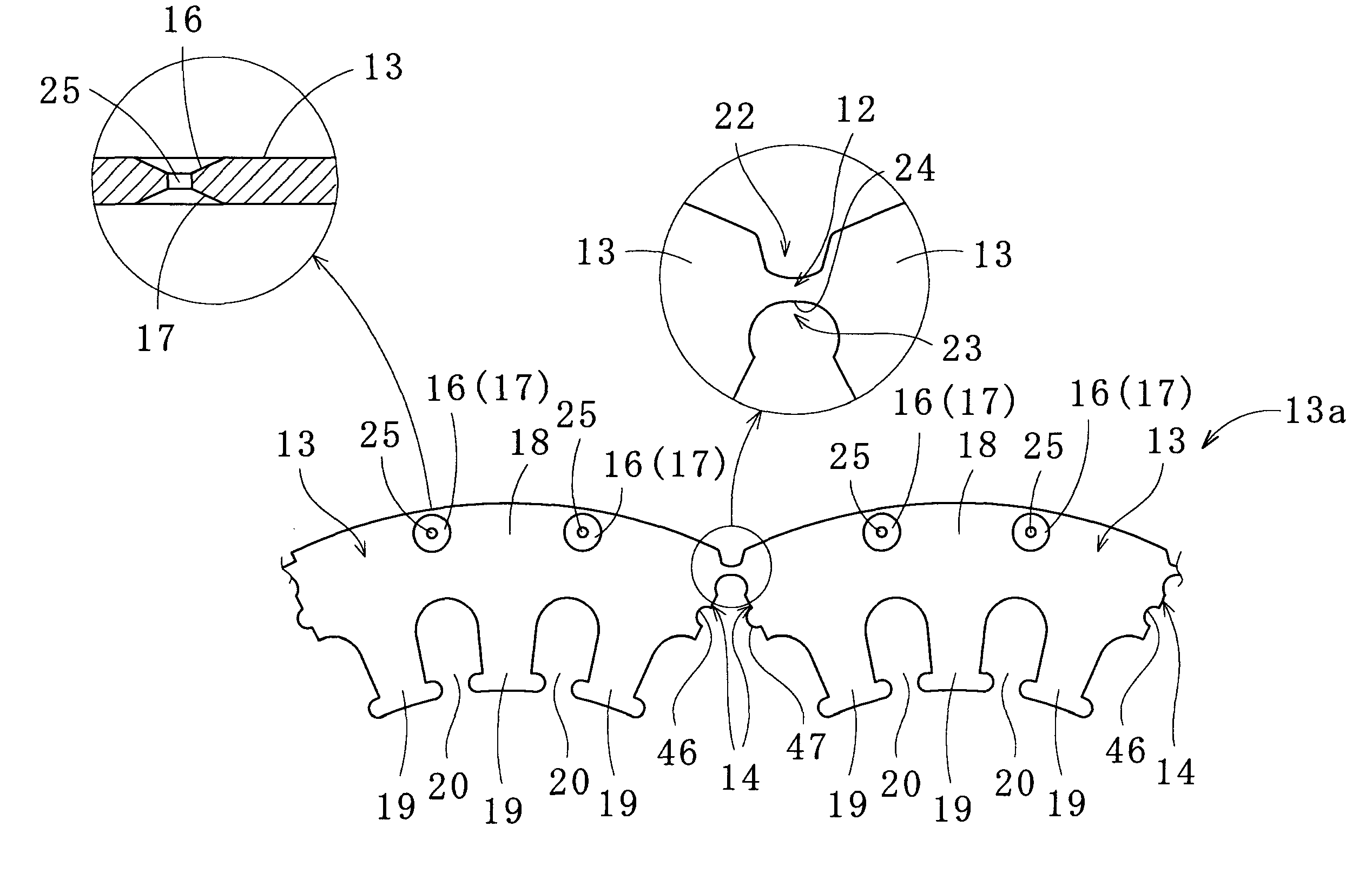
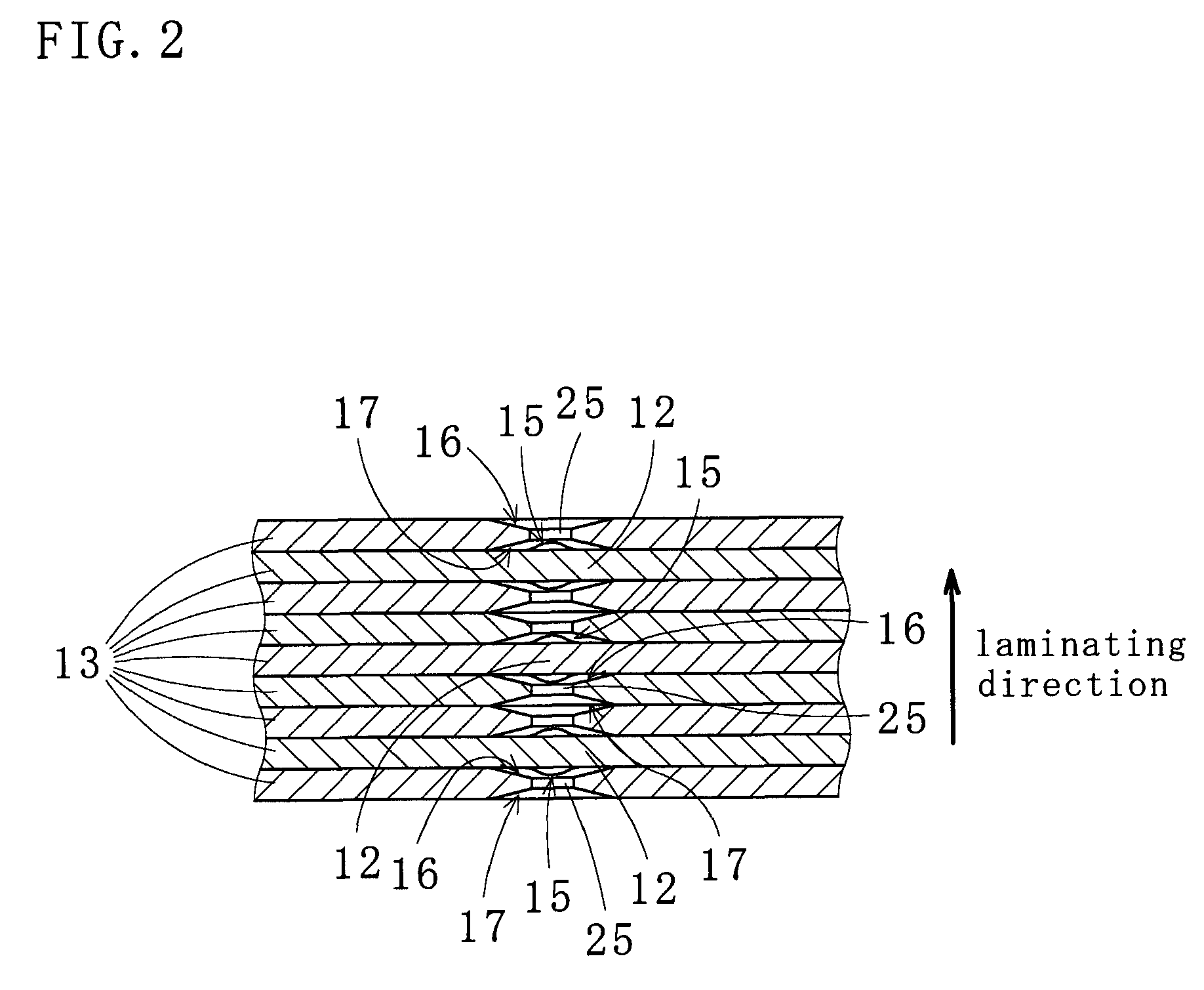
[0060]As illustrated in FIGS. 1 to 3, a laminated core 10 according to the present invention comprises a core sheet band 13a including segment core sheets 13 and connecting portions 12 for connecting the adjacent core sheets 13. The laminated core 10 is formed by spirally winding and laminating the core sheet band 13a while curving the connecting portions 12. It is preferable that radially inward sides (slots 20) or radially outward sides of the segment core sheets 13 are aligned with each other while the core sheets 13 are stacked one on another. In such a case, side edges 14 of the adjacent segment core sheets 13 may be slightly spaced apart from each other. Alternatively, the side edges 14 of the adjacent segment core sheets 13 may be fitted together (i.e., brought into close contact with each other) while the segment core sheets 13 are wound and laminated to wind the core sheet band 13a.

[0061]When the connecting portions 12 are bent to position the continuous segment core sheet...

second embodiment

[0096]Referring to FIG. 5, a description will be made regarding a laminated core and a method for manufacturing the same according to the present invention. Segment core sheets 50 are spirally wound to produce a laminated rotor core (not shown). As illustrated in FIG. 5, each segment core sheet 50 includes, in an area radially outward of a yoke section 51, a plurality of (in this embodiment, two) permanent-magnet insertion holes 52, 53, an example of permanent-magnet mounting sections. The permanent-magnet insertion holes 52, 53 are to be magnetic poles of the rotor.

[0097]The yoke sections 51 of the adjacent segment core sheets 50 are connected by connecting portions 55 located in an outer peripheral area 54. The outer peripheral area 54 is an area having a radial width equal to 1 / 30 to ⅕ (or 1 / 30 to ½), of the maximum radial width of the segment core sheet 50, from the outer periphery of the segment core sheet 50 to radially inward thereof. Formed on the radially outward side of th...


PUM

PropertyMeasurementUnit
thicknessaaaaaaaaaa
central angleaaaaaaaaaa

Abstract

A laminated core 10 including a plurality of segment core sheets 13 spirally wound and laminated in layers while connecting portions 12 connecting the adjacent segment core sheets 13 are bent, ends of the segment core sheets 13 are aligned with each other and the connecting portions 12 in the adjacent layers are circumferentially displaced relative to each other, the connecting portions 12 located in outer peripheral areas 11 of the segment core sheets 13, the laminated core 10 comprising:
    • a concave cutout 22 formed on a radially outward side of the connecting portion 12, the concave cutout 22 accommodating a radially expanded part 21 within an outer circle of the laminated core 10, the radially expanded part 21 formed in the connecting portion 12 radially outward at the bending of the connecting portion 12;
    • an interior cutout 23 formed on a radially inward side of the connecting portion 12, the interior cutout 23 defining a bent position of the connecting portion 12; and
    • depressed receptacles 16, 17 respectively formed on a top side and a bottom side of a radially outward area of the segment core sheet 13 except for the connecting portions 12, the depressed receptacles 16, 17 each receiving a thickness-direction expanded part 15 formed in the connecting portion 12 in a thickness direction thereof at the bending of the connecting portion 12.

Description

TECHNICAL FIELD[0001]The present invention relates to a laminated core and a method for manufacturing the same, the laminated core being formed by spirally winding and laminating plural segment core sheets connected by connecting portions. The term “laminated core” as used herein refers to a stator and a rotor used for a motor and a generator.BACKGROUND ART[0002]Conventionally, to improve yield of core materials used for production of laminated cores, a method of producing wound cores has been known which includes punching out plural segment core sheets connected in a band shape from a magnetic steel strip, and winding and laminating the band of core sheets. Production of the wound cores does not employ blanking of annular shaped core sheets from a core material. In particular, as disclosed in Patent Documents 1 to 3, for example, arc-shaped segment core sheets connected by connecting portions are punched out of a core material by means of die devices. The segment core sheets each h...

Claims


Application Information

Patent Timeline
Patent Type & Authority Applications(United States)
IPC IPC(8): H02K1/16H02K15/02
CPCH02K1/148Y10T29/49009H02K15/02
Inventor MYOJIN, IWAO
Owner MITSUI HIGH TEC INC
Why Eureka
Try Eureka