
Self-locating fastener and method

Inactive Publication Date: 2005-03-22
NORTHROP GRUMMAN SYST CORP
View PDF25 Cites 15 Cited by
  • Summary
  • Abstract
  • Description
  • Claims
  • Application Information

AI Technical Summary

Benefits of technology

The invention has several important technical advantages. Various embodiments of the invention may have none, some or all of these advantages. The present invention may reduce fabrication and labor costs for various structures. Self-locating fasteners may also hold tubes and conduits at nominal position, thereby preventing clearance issues and improving assembly. Additional advantages may include low part cost, real-time fabrication, more complex tube routing, and less drilling on assembly. Other technical advantages of the present invention will be readily apparent to one skilled in the art.

Problems solved by technology

These holes reduce the life expectancy of the primary structure.
Additionally, drilling holes and inserting rivets is time consuming and costly.
Due to installation variations, mislocated sheet metal fasteners may cause clearance issues or other assorted problems during assembly of the structure.

Method used


Image

  • Self-locating fastener and method
  • Self-locating fastener and method
  • Self-locating fastener and method

Examples


Embodiment Construction

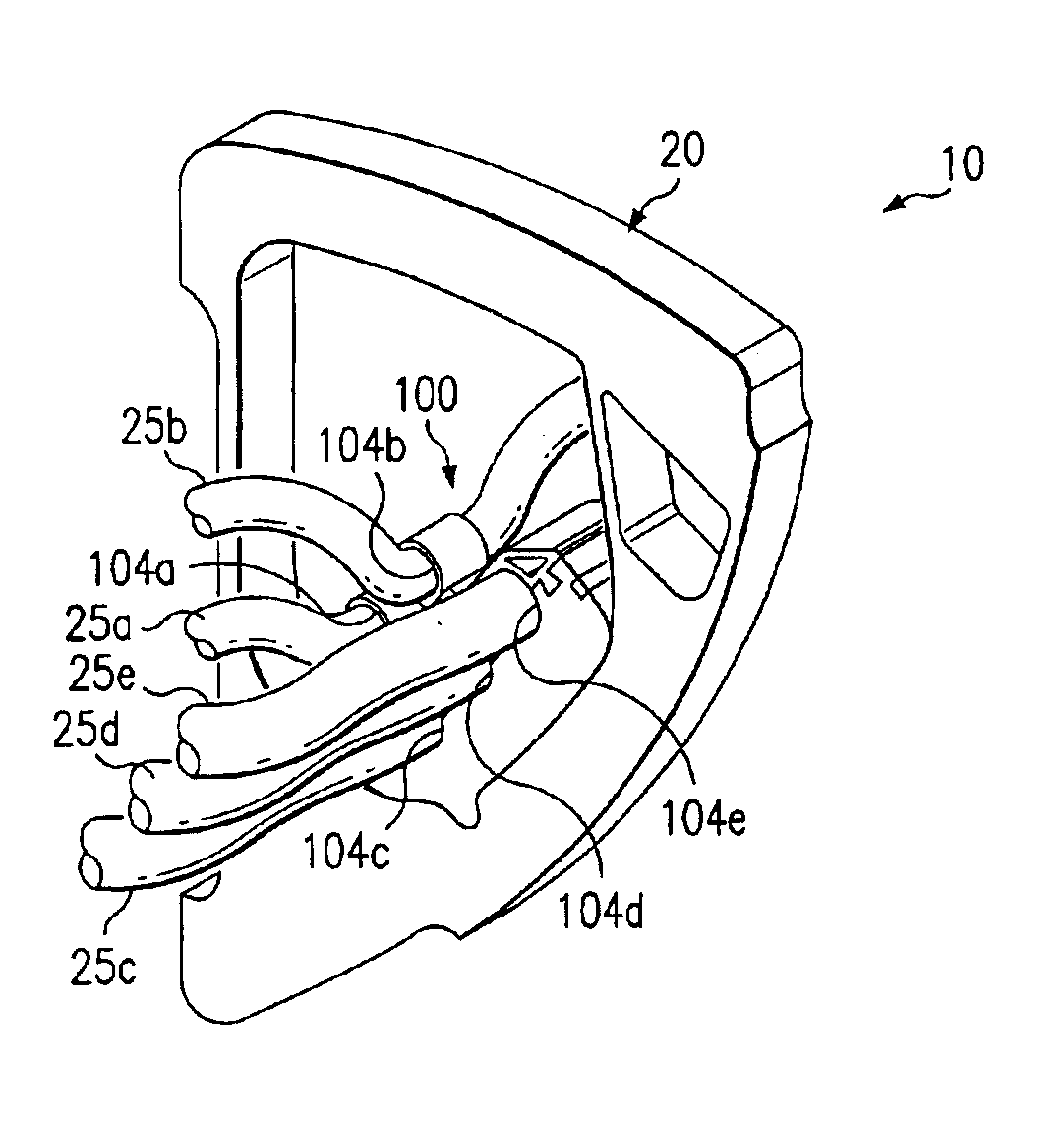
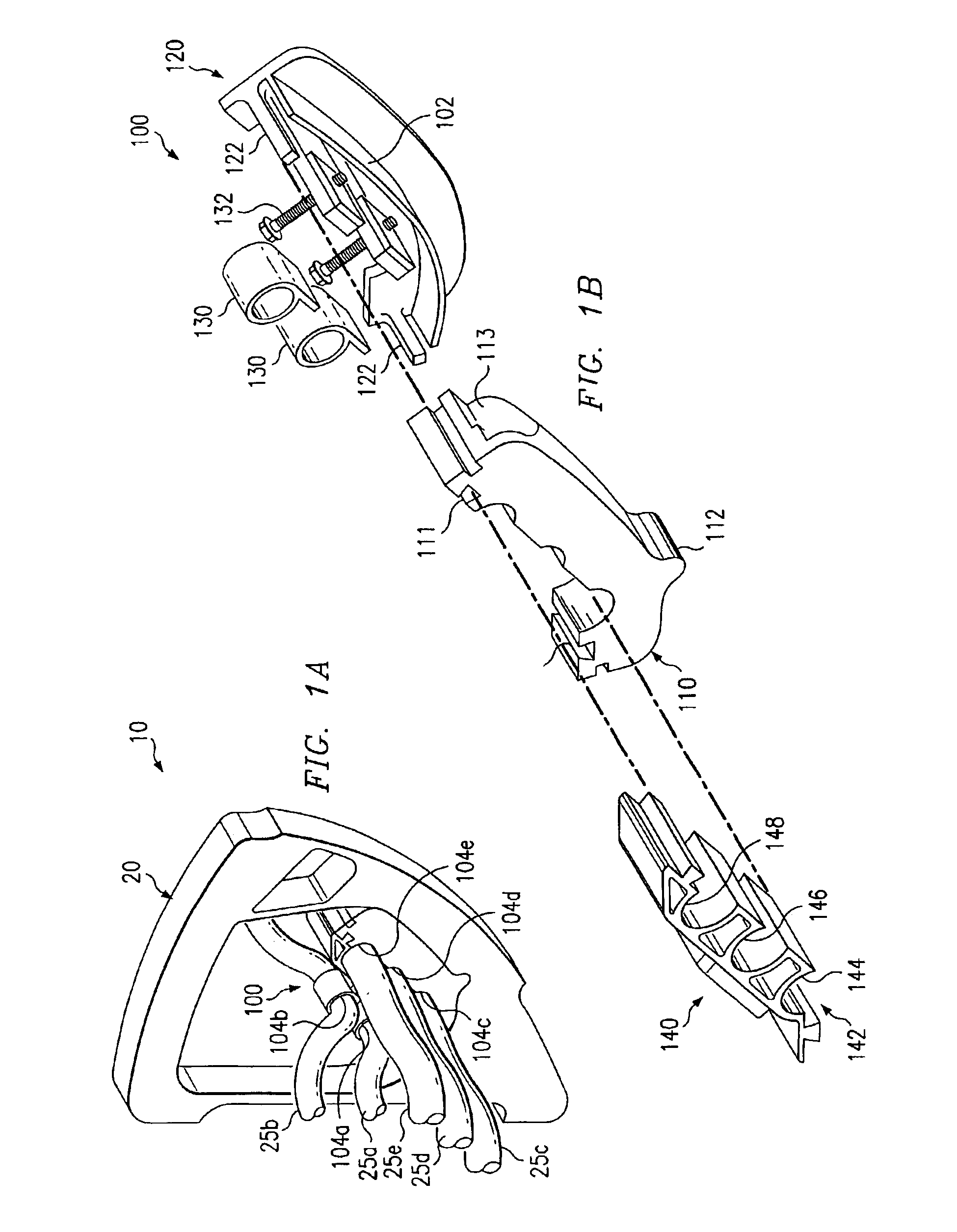
FIG. 1A illustrates one embodiment of a system 10 including a self-locating fastener 100 constructed in accordance with the present invention. In the illustrated embodiment, system 10 includes the fastener 100, tubes 25a-e, and frame 20. Other embodiments of system 10 may be used without departing from the scope of this disclosure.

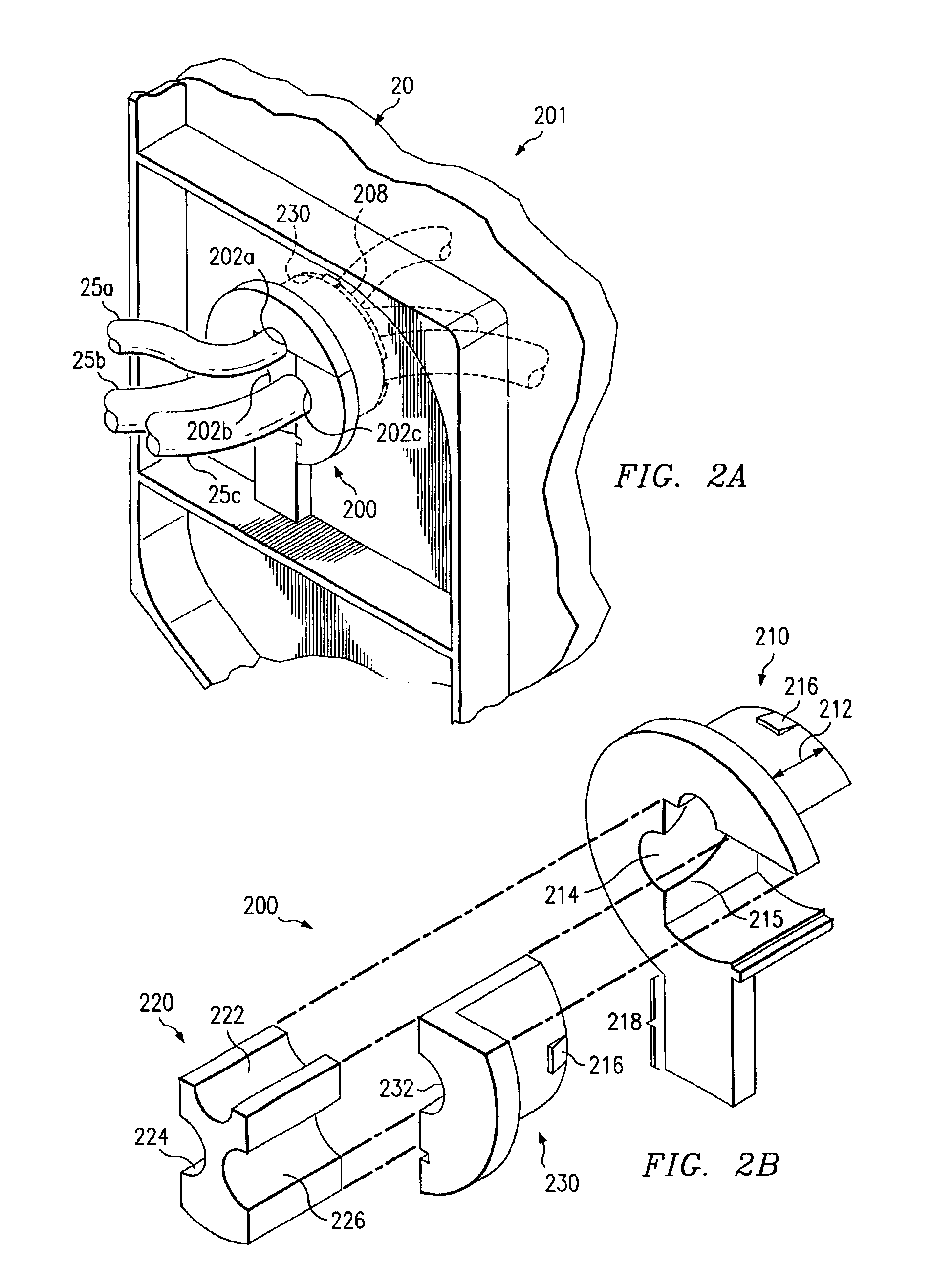
Tubes 25a-e may comprise a first contoured surface that includes a plurality of shapes. Tubes 25a-e may be fuel tubes, hydraulic tubes, sensors, electrical conduits, penetrating a portion of frame 20, or any other internal assemblies that may be used, in part, to form an inner contoured surface of fastener 100 (or fastener 200 described below). It will be understood that tubes 25a-e are for example only. Tubes 25a-e may be generally referred to as tubes 25 and may include any number of tubes. Frame 20 may comprise a second contoured surface that includes a plurality of shapes. Frame 20 may include a cap, a web, a rib, a bulkhead, a tube 25 adjacent to the ...


PUM


Abstract

A method of forming a self-locating fastener includes determining a shape of a first contoured surface and a shape of a second contoured surface. The method continues by determining an offset of the shape of the first contoured surface and an offset of the shape of the second contoured surface. An inner contoured surface of a fastener is formed having a shape based at least in part on the offset of the shape of the first contoured surface. An outer contoured surface of the fastener is formed having a shape based at least in part on the offset of the shape of the second contoured surface. The fastener is operable to self-locate on the first and second contoured surfaces.

Description

TECHNICAL FIELD OF THE INVENTIONThis invention relates generally to techniques for forming fasteners and, more particularly, to self-locating fasteners.BACKGROUND OF THE INVENTIONVarious structures, like aircraft, have requirements for wire harnesses, fuel tubes, hydraulic tubes, electrical conduits, and other internal assemblies to have rigid support points at certain intervals. Currently, sheet metal fasteners are used to support the wire harnesses or tubes. The sheet metal fasteners generally are attached to the primary structure by drilling holes and inserting rivets. These holes reduce the life expectancy of the primary structure. Additionally, drilling holes and inserting rivets is time consuming and costly. Due to installation variations, mislocated sheet metal fasteners may cause clearance issues or other assorted problems during assembly of the structure.SUMMARY OF THE INVENTIONOne aspect of the invention is a method for forming a self-locating fastener. The method includes...

Claims


Application Information

Patent Timeline
IPC IPC(8): F16L3/22F16L3/233F16L5/00H02G3/22
CPCF16L3/2332H02G3/22F16L5/00Y10T16/05B33Y80/00
Inventor DIGGS, PAUL BARTH
Owner NORTHROP GRUMMAN SYST CORP
Learn More