

Method and apparatus for radome and reflector dish interconnection
a technology of radome and reflector, which is applied in the field of microwave reflector antennas, can solve the problems of limiting interchangeability and/or replacement, increasing the total number of discrete components, and requiring additional threading/tightening assembly steps,
- Summary
- Abstract
- Description
- Claims
- Application Information
AI Technical Summary
Benefits of technology
Problems solved by technology
Method used
Image

Examples
Embodiment Construction
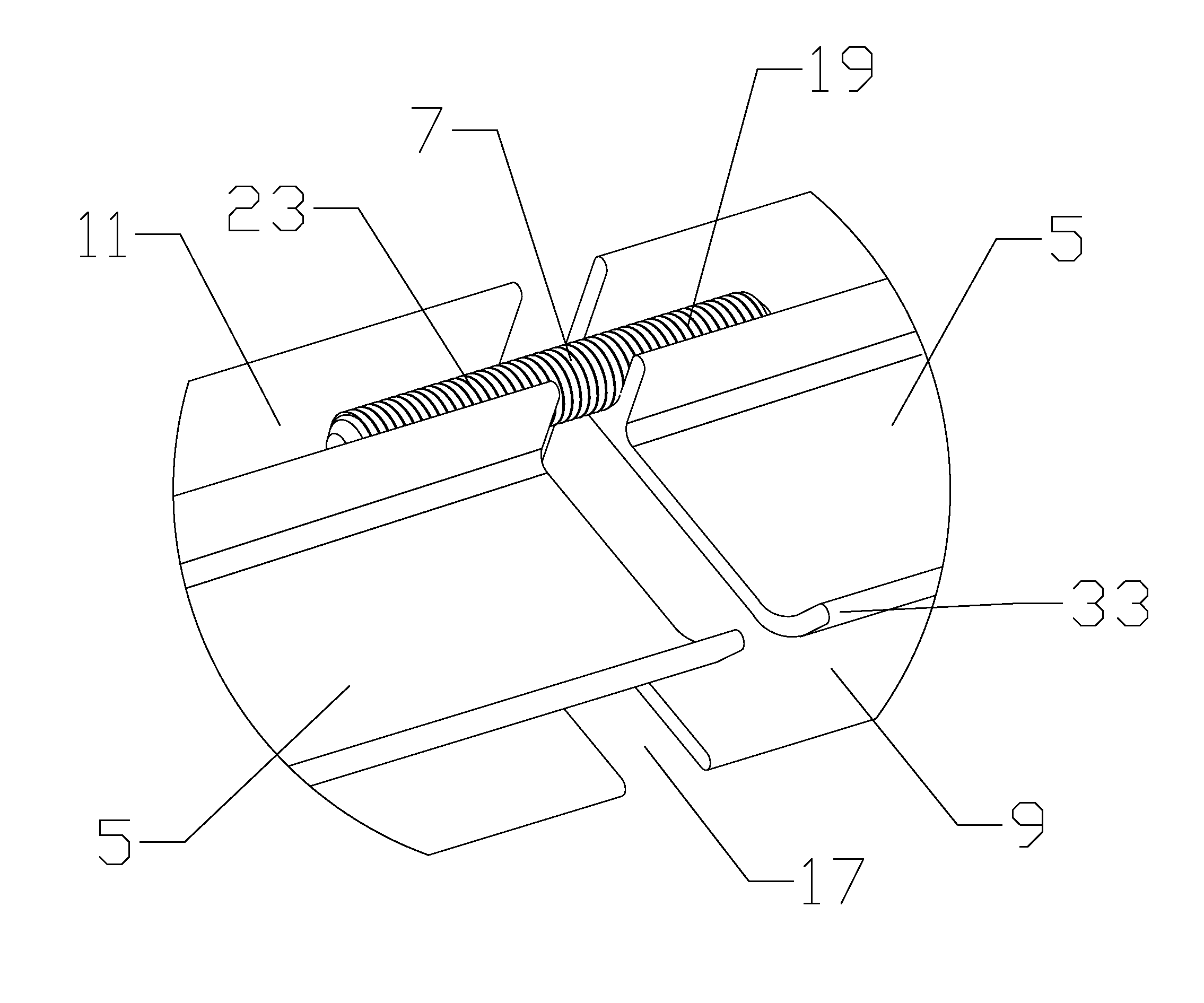
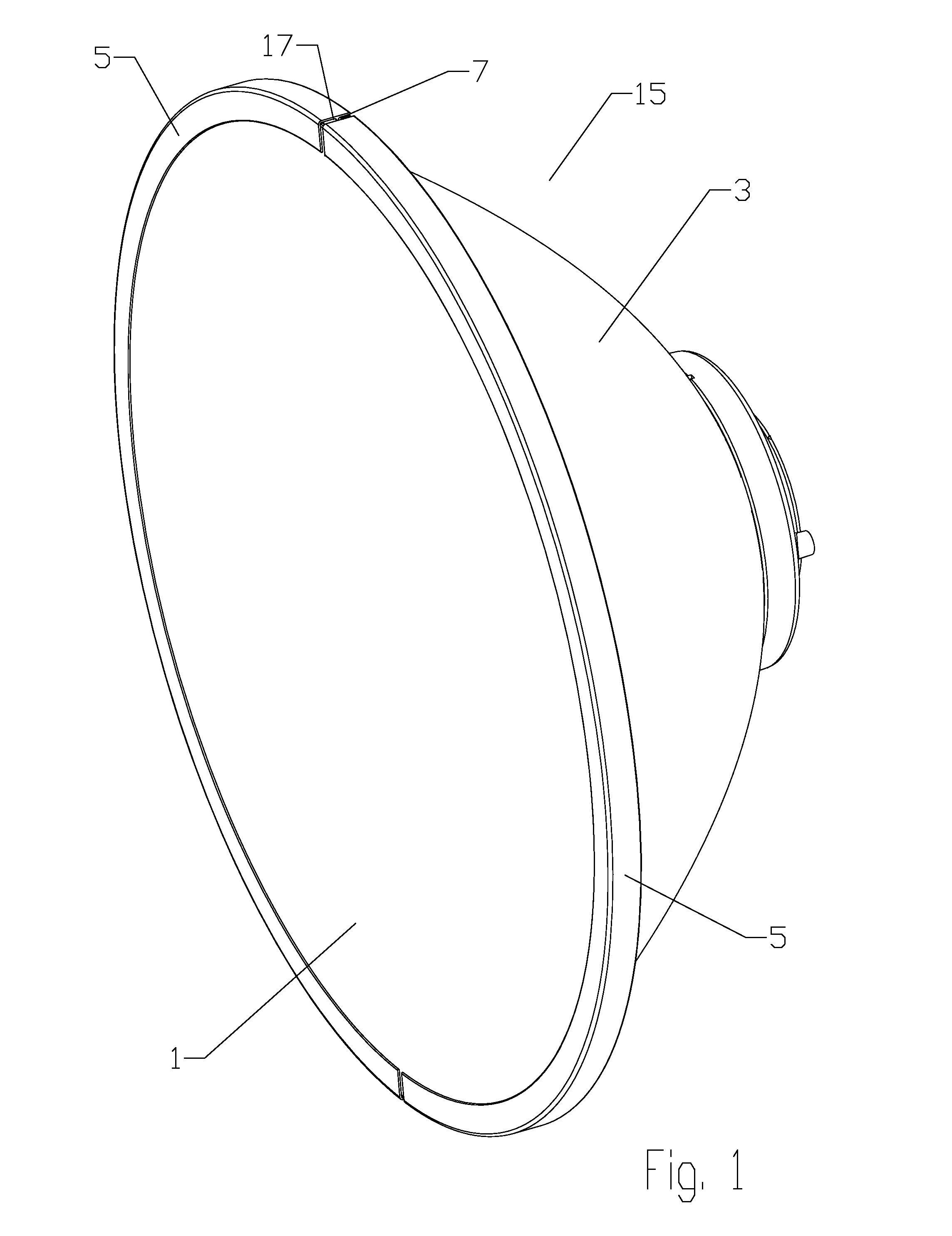
[0015]A radome 1 is retained on reflector dish 3 via a permanent band clamp type interconnection that may be cost efficiently formed by crimping a plurality of curved channel portions 5 end to end around a shared link member 7, for example as shown in FIG. 1. Thereby, a reliable permanent interconnection may be cost efficiently formed from a minimum number of simplified parts, which may enable significant materials, manufacturing and / or installation efficiencies.
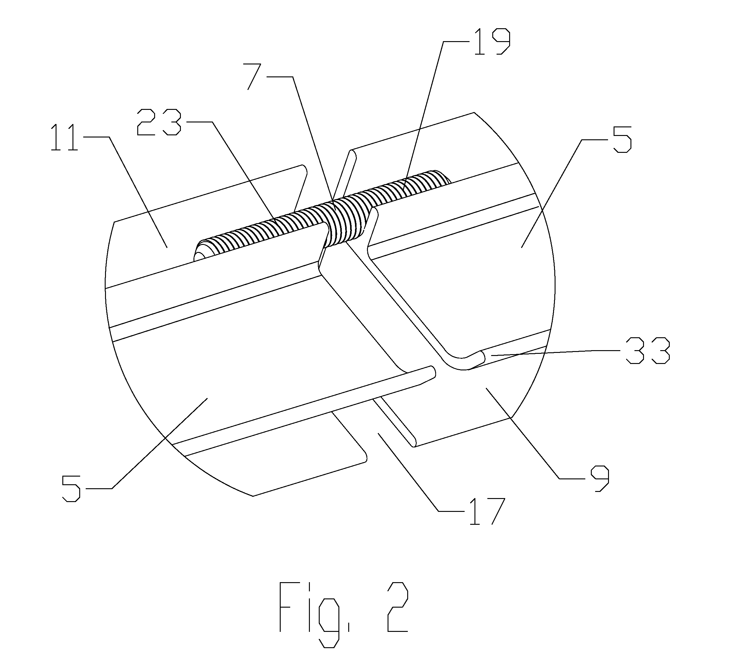
[0016]As best shown in FIGS. 2-5, the channel portions 5 are provided with an open periphery slot 9 and an open retention slot 11. The periphery slot 9 is dimensioned to receive the periphery of the radome 1 and the periphery of the reflector dish 3 seated upon one another. The channel portions 5 are arranged end-to-end adjacent to one another, encircling the periphery of the radome 1 and the periphery of the reflector dish 3 seated within the periphery slot 9. A gap 17 may be provided between each channel portions 5 are arr...
PUM
| Property | Measurement | Unit |
|---|---|---|
| outer diameter | aaaaa | aaaaa |
| electrical performance | aaaaa | aaaaa |
| outer diameters | aaaaa | aaaaa |
Abstract
Description
Claims
Application Information