

Electric cell connector for a battery module
- Summary
- Abstract
- Description
- Claims
- Application Information
AI Technical Summary
Benefits of technology
Problems solved by technology
Method used
Image

Examples
Embodiment Construction
[0022]Identical reference symbols denote identical device components in all the figures.
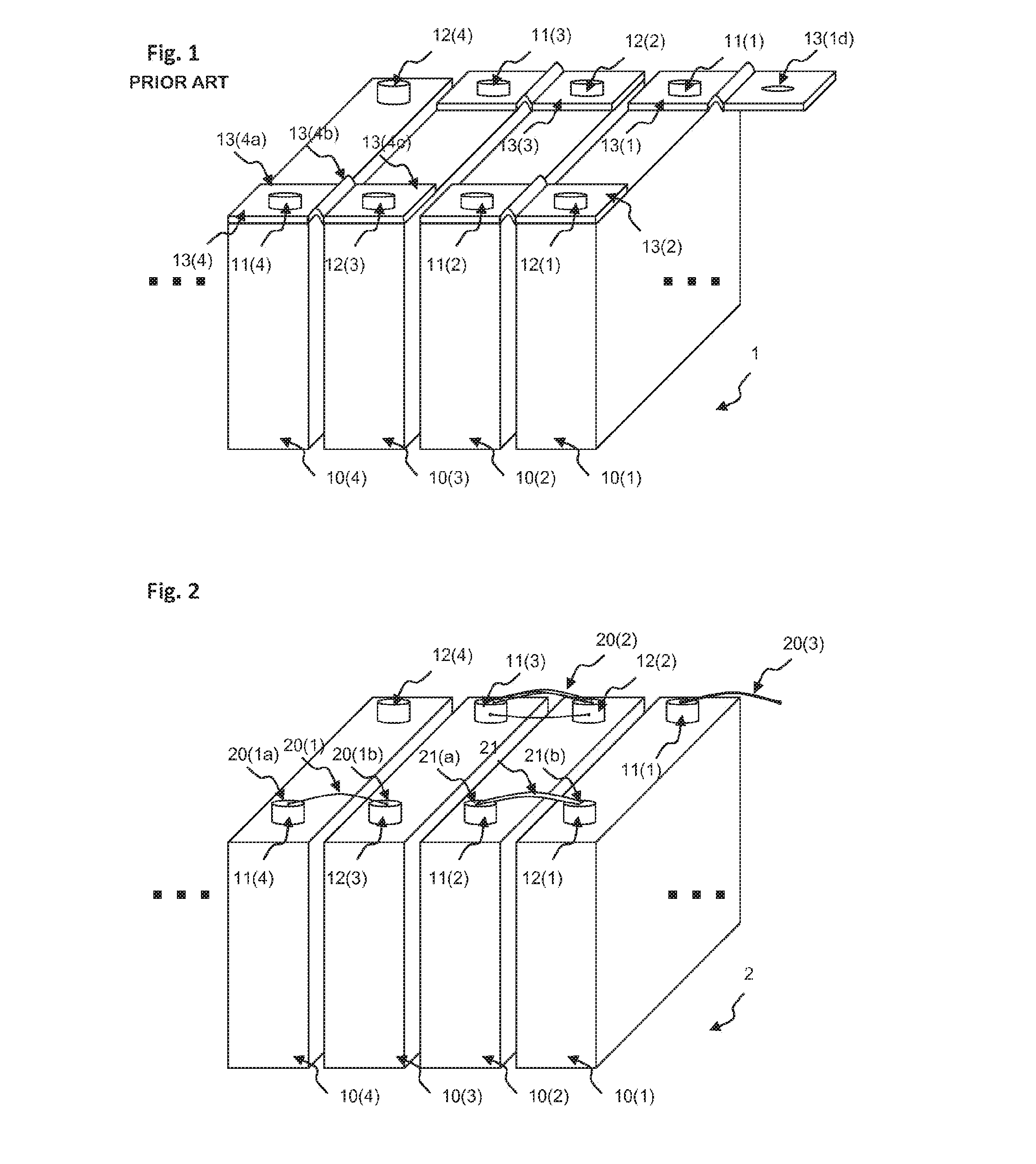
[0023]FIG. 1 shows four battery cells 10(1), 10(2), 10(3), 10(4) of a battery module 1 with cell contacts 11(1), 11(2), 11(3), 11(4), 12(1), 12(2), 12(3), 12(4) which are connected to one another in an electrically conductive manner via electric cell connectors 13(1), 13(2), 13(3), 13(4) resulting in a series connection of the battery cells 10(1), 10(2), 10(3), 10(4), according to an embodiment in accordance with the prior art. For example, the positive pole of the battery cell 10(1) is connected by means of the cell contact 12(1) via the electric cell connector 13(2) to the negative pole of the battery cell 10(2) by means of the cell contact 11(2).
[0024]The electric cell connector 13(4) comprises a first connecting element 13(4a), a second connecting element 13(4c) and a bent connecting element 13(4b) which electrically contacts the first connecting element 13(4a) to the second connecting elemen...
PUM
| Property | Measurement | Unit |
|---|---|---|
| Diameter | aaaaa | aaaaa |
| Diameter | aaaaa | aaaaa |
| Length | aaaaa | aaaaa |
Abstract
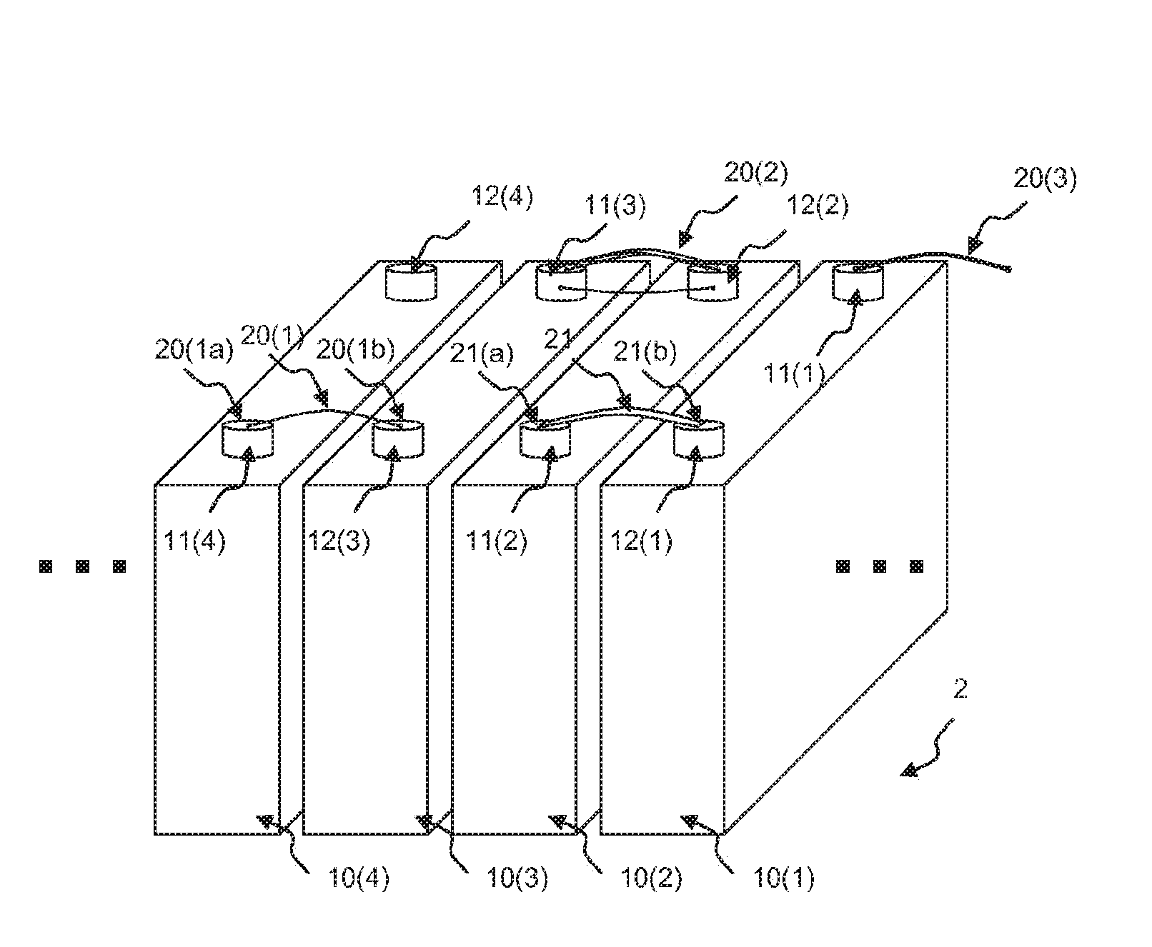
Description
Claims
Application Information