Drive System for Vehicle

a technology for driving systems and vehicles, applied in the direction of vehicle transmission, rider propulsion, chain/belt transmission, etc., can solve the problems of poor performance, significant maintenance cost, and position of pedals, and achieve the effect of high initial speed, short time, and constant speed

Inactive Publication Date: 2010-09-02
PADILLA OROZCO GABRIEL
View PDF37 Cites 7 Cited by
  • Summary
  • Abstract
  • Description
  • Claims
  • Application Information

AI Technical Summary

Benefits of technology

[0014]The aim of the present invention is to provide a drive system for a land transport vehicle which

Problems solved by technology

Also, the arrangement proposed here presents a disadvantage in their design since the position of the pedals is uncomfortable.
Moreover, the components of this system are susceptible to accelerated wear and therefore an early break of the same, resulting in a significant maintenance cost.
The disadvantages found in the document are: first, for starting the vehicle essential to use an internal combustion engine, and if this engine has not a properly functioning vehicle starting, it will not occur properly, coupled with the fact that the number countless chains and sprockets where chains are assembled is inappropriate, since a larger number of chains functioning would sometimes dependent on the good activity of the chains and sprockets for it.
This document describes a mechanism that is based on combining gears, pulleys, chains strengths which

Method used


Image

  • Drive System for Vehicle
  • Drive System for Vehicle
  • Drive System for Vehicle

Examples


first embodiment

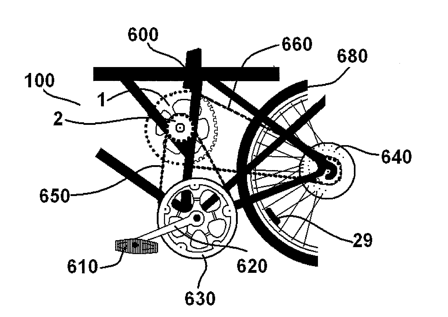
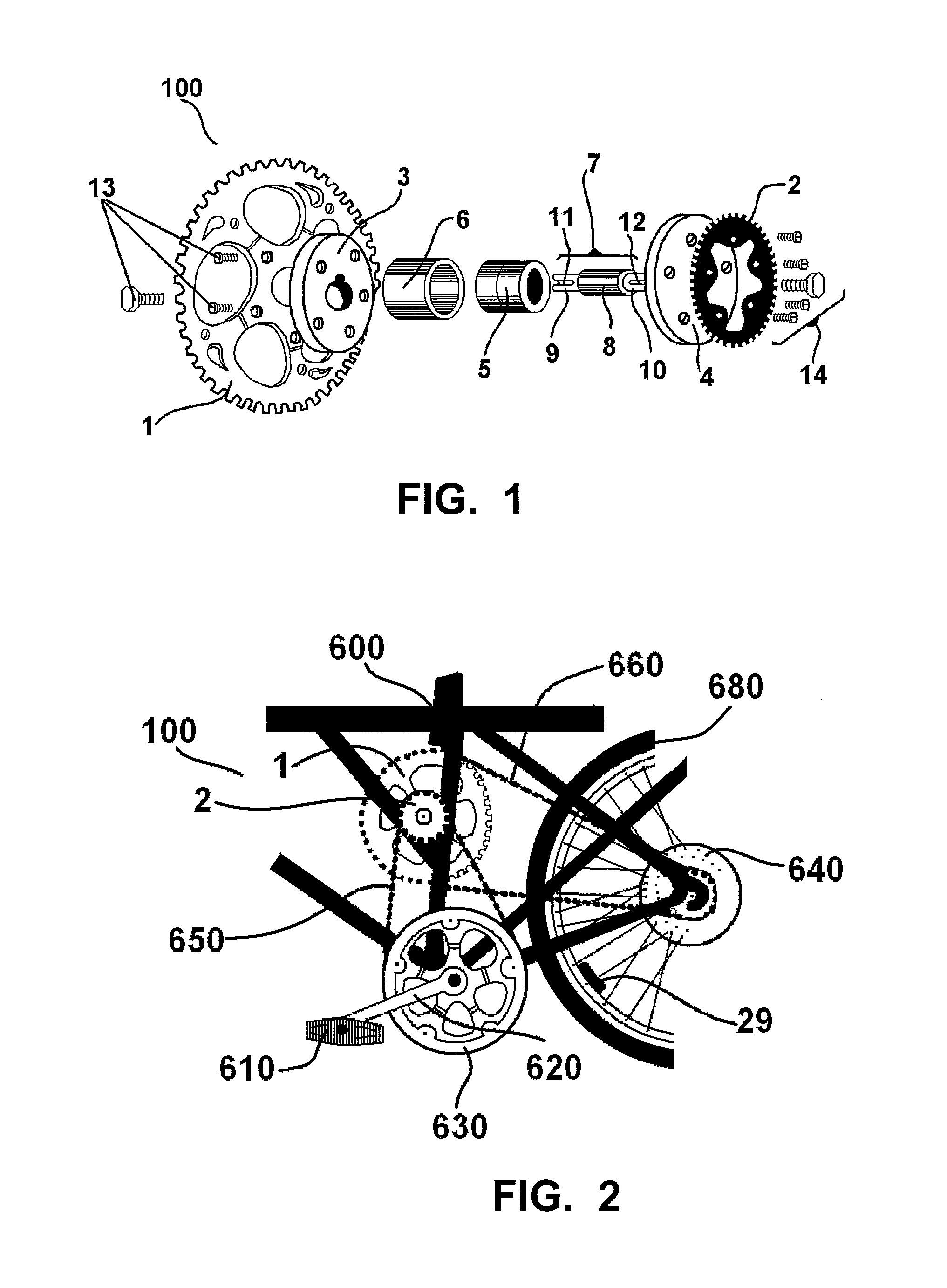
[0035]For a better understanding of the invention, the principles of the same applied to a human-powered vehicle, especially on a bike, are described herein. Thus, in the invention, illustrated in FIGS. 1 and 2, the drive shaft 100 is composed of two sprockets, one with a great diameter 1 and another one with a diameter less than the other 2 (or equivalently, with fewer teeth), two support hubs 3 and 4 on which the sprockets 1 and 2 are fixed, respectively, by fasteners 13 and 14; two bearings 5 inserted inside a bearingholder 6. A shaft 7 with a diameter equal to the diameter of the bearings 5, to which are tightly coupled, under pressure, taking the shaft 7 a length divided into three sections, namely, a central part 8 which supports the bearings 5 and two ends 9 and 10 of smaller diameter which serve to cap and support the support hubs 3 and 4 joined with the two sprockets 1 and 2, where the function of the support hubs 3 and 4 support is to keep the sprockets 1 and 2 perpendicul...

third embodiment

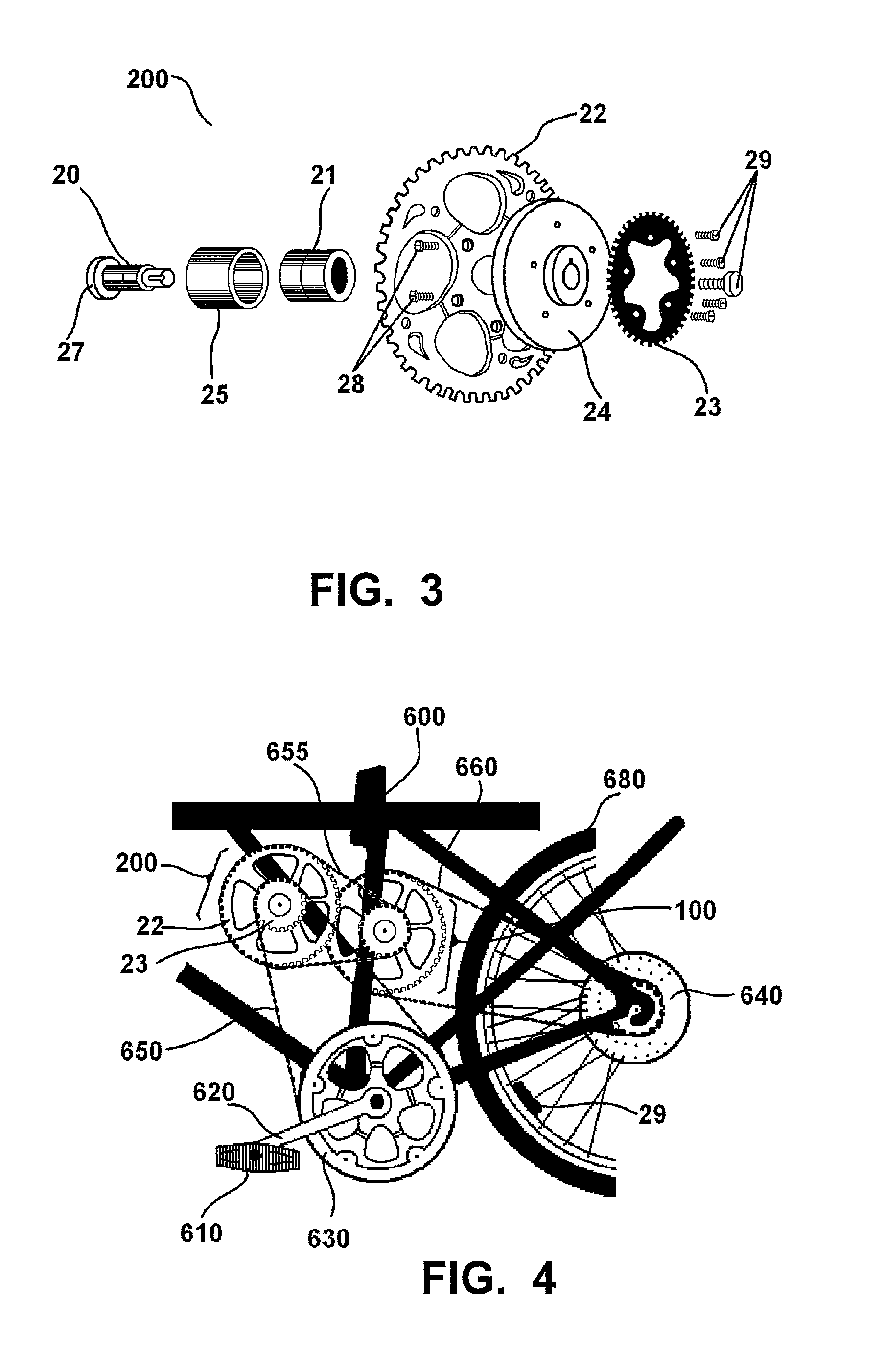
[0042]the present invention comprises a drive shaft 300, which by its assembly allows a different configuration to the above mentioned embodiments; FIG. 5 illustrates the components of the drive shaft 300 that consists of 5 elements and fixing means 31, such as screws. The central section of the shaft 30 is of the same diameter as of the inside diameter of the bearings 32 which have a separator between them, to provide greater stability to them in response to the pressure at which they are submitted; said shaft 30 in its first section 36 has a length which enables it to couple with the inside part of the bearings 32, these bearings 32 being received within the bearingholder 33 which help supporting the force applied to start the vehicle movement. Also, at the far end of the shaft 30 is located a smaller diameter section 34 at the end of which has a keyway 35 to hold and avoid slippage of the pair formed by the larger sprocket 38 and the smaller sprocket 37; continuous to the smaller...

embodiment 1

II. Embodiment 1 with the Drive Shaft 100

[0064]Since the movement provided by the rider to pedal and transmitted by him to the central star 630 is transmitted to the smaller sprocket 2 of the drive shaft 100 via chain 650, as illustrated in FIG. 2, the first transmission relationship is produced between these two elements 630 and 2; the smaller sprocket 2 then turns to the larger sprocket 1 in a direct link through the shaft 7, and the larger sprocket 1 finally transmits motion to the pinion gear 640 by chain 660, setting the second transmission ratio 1-640, so we have:

[(N630n2)*(N1n640)](6)

which can be rearranged to:

[(N630n640)*(N1n2)](7)

so the vehicle speed would be increased, keeping other factors constant, in an amount equal to the ratio between the number of teeth on the smaller sprocket 2 and the number of teeth on the larger sprocket shaft 2 of the drive shaft 100 intermediate to the central star 630 and the pinion gear 640 that moves the wheel 680. It is said that there is a...


PUM


Abstract

A drive system for vehicles which do not use engines or batteries, such as road vehicles, with two or more wheels. The system relies on the incorporation of one or more drive shafts including a common shaft, and two sprockets, one with a fewer number of teeth and another with a greater number of teeth. The shafts extend between the central star and the pinion gear of the vehicle that moves the drive wheel so that the motion from the central star is transmitted to the smaller sprocket by the first shaft, and then from the larger sprocket of the shaft to the smaller sprocket of the next shaft and so on up to the pinion gear. With this system, the vehicle speed is increased many times as the product of relations between larger and smaller gears of each drive shaft in the number of shafts are used.

Description

FIELD OF THE INVENTION [0001]The present invention is applicable in the field of transport or sports vehicles, mechanically activated by pedals, cranks, wheels or similar, especially vehicles with 2 or more wheels such as bicycles, wheelchairs, boats, etc.BACKGROUND OF THE INVENTION[0002]For several years all efforts to improve the movement of the mechanically driven vehicles such as bicycles and the like, has focused on providing lighter materials for construction, in order to give the vehicle a low overall weight, allowing the user to starting it, putting less effort. Furthermore, innovations have been provided so that the complete body of the vehicle can have an easy assembly, including modifications to the systems of shafts, a combination of pulleys, chains and gears without that, to date, any outstanding results has achieved in increasing speed with less effort.[0003]There are some documents disclosing various devices designed to reduce the user effort, including patents from M...

Claims


Application Information

Patent Timeline
IPC IPC(8): B62M9/00
CPCB62M9/04B62M9/02
Inventor PADILLA OROZCO, GABRIEL
Owner PADILLA OROZCO GABRIEL
Why Eureka
Try Eureka