Injection apparatus and molding method in injection molding machine

A technology of injection molding machine and injection device, which is applied in the field of molding, can solve problems such as insufficient filling and low-pressure molding, and achieve the effects of suppressing defects, preventing insufficient filling, and easy filling

Inactive Publication Date: 2004-01-14
FANUC LTD
View PDF0 Cites 1 Cited by
  • Summary
  • Abstract
  • Description
  • Claims
  • Application Information

AI Technical Summary

Problems solved by technology

This is the main cause of defects such as underfill and dents on molded products
This phenomenon is obvious when the gain is adjusted so

Method used


Image

  • Injection apparatus and molding method in injection molding machine
  • Injection apparatus and molding method in injection molding machine
  • Injection apparatus and molding method in injection molding machine

Examples


Embodiment Construction

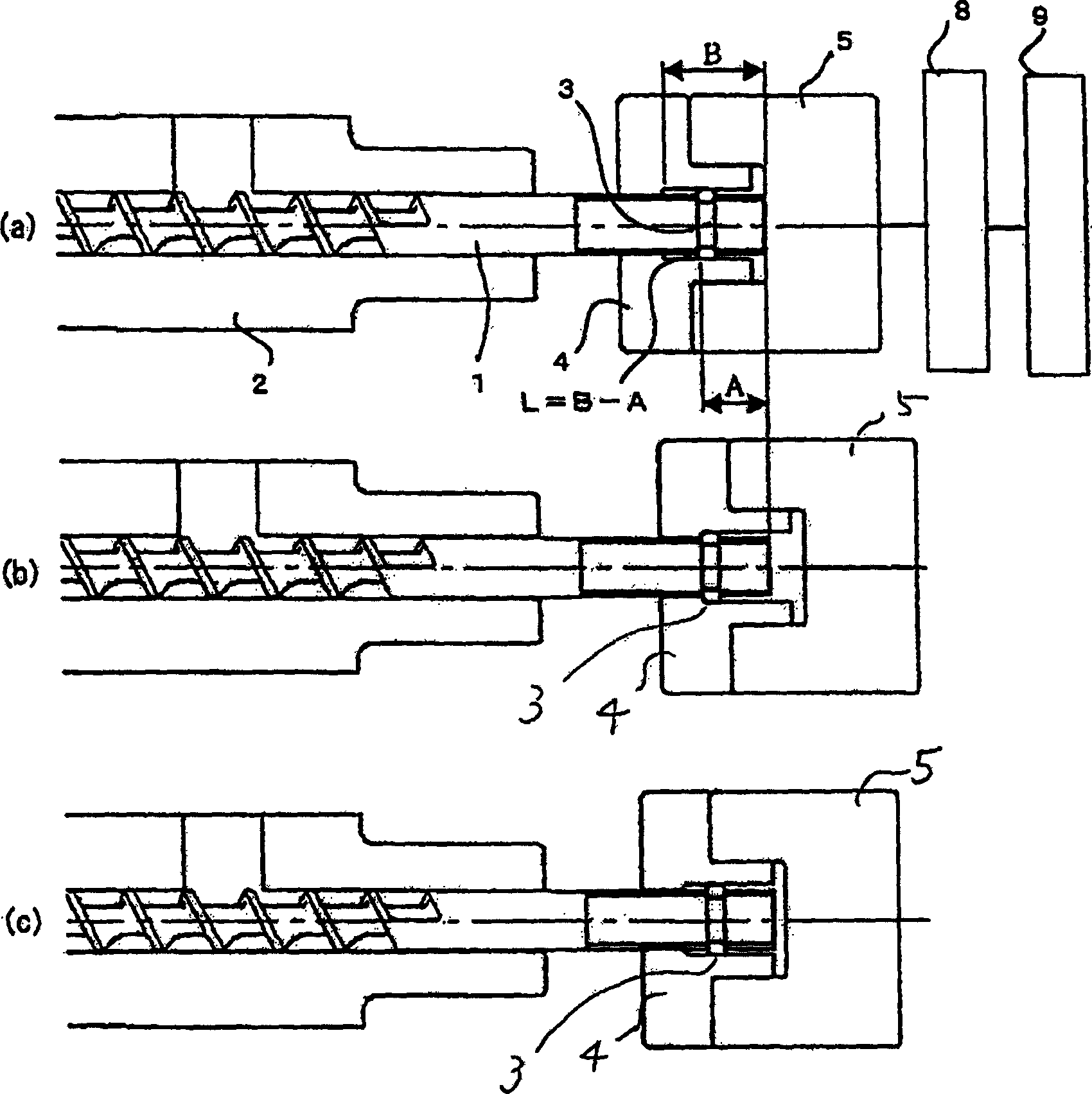
[0024] figure 2 It is a schematic diagram of the connection relationship between the screw and the screw mounting part in the first embodiment of the present invention. and, with figure 1 The same elements of the shown prior art examples are denoted by the same symbols. And, with figure 1 The original example shown is the same, the bushing 4 and the sleeve 5 are secured by bolts, figure 2 Bolts are omitted.

[0025] In this first embodiment, a dead zone in which the two can move relative to each other is set between the screw 1 and the screw mounting part composed of the sleeve 5 and the bushing 4, and figure 1 The conventional example shown is different. That is, if figure 2 As shown, the stop ring 3 provided on the screw 1 will not contact the stop ring restraining face of the bush 4 even when the terminal surface of the screw 1 is in contact with the face of the sleeve 5 . That is to say, the stop ring 3 will not be squeezed by the sleeve 5 and the bush 4 . The s...


PUM


Abstract

An injection apparatus in an injection molding machine transmits a drive force generated by an injecting servomotor to a screw through a drive force transmitting mechanism to move the screw for performing injection. In addition, the injection apparatus has a dead zone of movement provided by a predetermined distance in the range of the injecting servomotor to the screw.

Description

technical field [0001] The present invention relates to an injection device of an injection molding machine and a molding method using the same. Background technique [0002] In conventional injection molding machines, in order to control the free movement of the screw in the direction of its axis, the screw and the screw shaft driver are combined in such a way that the driving force transmission mechanism transmits the force linearly. figure 1 Shown is the screw joint of a conventionally used general injection device. [0003] figure 1 Among them, a stop ring 3 is provided at the rear end of the screw 1 inserted into the barrel 2 . The stop ring 3 is clamped by the sleeve 5 and the bush 4 that constitute the screw installation part, and then the sleeve 5 and the bush 4 are fixed with bolts 6, so that the installation of the screw 1 will not be installed relative to the screw. The part moves axially. At the same time, the rear end of the screw 1 and the bushing 4 are spl...

Claims


Application Information

Patent Timeline
IPC IPC(8): B29C45/17B29C45/50
CPCB29C2045/508B29C45/5008
Inventor 白石亘高次聪石黑俊夫
Owner FANUC LTD
Why Eureka
Try Eureka