Permanent magnet vacuum circuit breaker

A permanent magnet vacuum and circuit breaker technology, applied in the direction of high-voltage air circuit breakers, circuits, electrical components, etc., can solve the development trend that cannot adapt to the miniaturization of inflatable cabinets, there are many movement transmission links of the motion axis, and the overall structure is complex and large, etc. problems, to achieve the effect of improving assembly efficiency and process effect, ensuring reliability and operating stability, and ensuring transmission efficiency

Inactive Publication Date: 2021-04-30
MURGE ELECTRIC CO LTD
View PDF4 Cites 2 Cited by
  • Summary
  • Abstract
  • Description
  • Claims
  • Application Information

AI Technical Summary

Problems solved by technology

When the circuit breaker is working, the spring is in a load state for a long time, and the spring stiffness will be attenuated after a long time, which will affect the closing and opening output of the circuit breaker, resulting in the closing time and opening time of the circuit breaker. , Closing speed, opening speed, closing bounce, opening bounce and other parameters are too discrete or fail to meet the requirements of the circuit breaker
[0003] In addition, the circuit breaker connects the moving contact and the static contact through the moving shaft to perform closing and opening actions. Therefore, the efficiency of the moving shaft to transmit motion plays a very important role in the performance of the circuit breaker. The existing moving shaft There are many motion transmission links, the transmission efficiency is low, and the overall structure is complex and huge. It is suitable for medium and large inflatable cabinets and cannot adapt to the development trend of miniaturization of inflatable cabinets. This equipment effectively solves this problem

Method used


Image

  • Permanent magnet vacuum circuit breaker
  • Permanent magnet vacuum circuit breaker
  • Permanent magnet vacuum circuit breaker

Examples


Embodiment 1

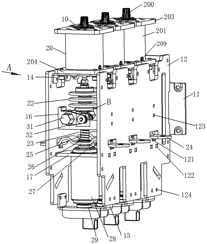
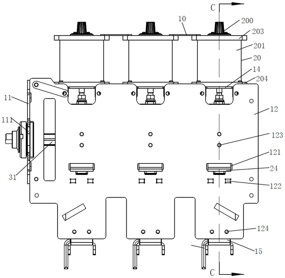
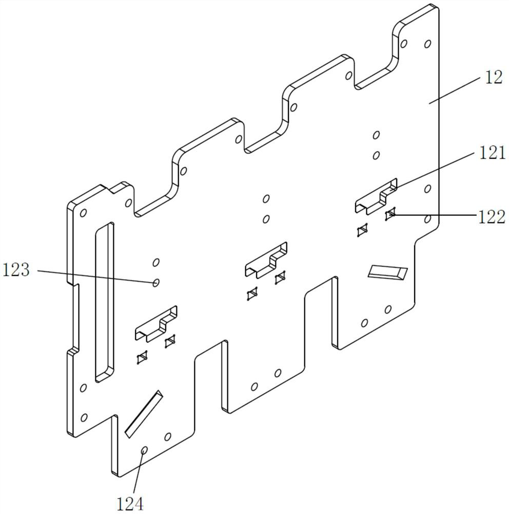
[0046]Such asFigure 1-18As shown, a permanent magnet vacuum circuit breaker, including a circuit unit and a receiving device for mounting the circuit unit, and the circuit unit comprises a permanent magnet mechanism 20, an insulating member 22, a connection assembly 23, a contact, a pressure spring 25, a conductive sheet 24, Vacuum arc interruption chamber 28, the switching and static contacts 29, and the same period, the permanent magnet mechanism 20 includes a dust cover 200 that the movable core tilt rod 206 and the anti-movable core tilt rod 206, the connection assembly 23 includes a first connecting rod 231, movable The core iron pulling rod 206 and the first connecting rod 231 are respectively provided with a milling, and the same assembly includes the same shaft 31, the transmission pin 33, the same seating seat 16, and the same period of the arm 32, respectively, respectively, respectively, respectively, respectively, the same axis 31 and the transmission pin 33 guide .

[0047...


PUM


Abstract

The invention discloses a permanent magnet vacuum circuit breaker which comprises a circuit breaking unit and a bearing device used for installing the circuit breaking unit, the circuit breaking unit comprises a permanent magnet mechanism, an insulating part, a connecting assembly, a contact pressure spring, a conducting strip, a vacuum arc-extinguishing chamber, a switch static contact and a synchronizing assembly, and the permanent magnet mechanism comprises a movable core iron pull rod and a dustproof cover used for protecting the movable core iron pull rod. The connecting assembly comprises a first connecting rod, the movable core iron pull rod and the first connecting rod are each provided with a milled flat structure, the synchronizing assembly comprises a synchronizing shaft, a transmission pin, a synchronizing base and a synchronizing contact arm, and the synchronizing base guides the synchronizing shaft and the transmission pin. According to the permanent magnet vacuum circuit breaker, a direct driving design is adopted, many transmission links are reduced, the energy consumption is reduced, and the transmission efficiency is ensured to the maximum extent. The permanent magnet vacuum circuit breaker disclosed by the invention is designed to be integrally miniaturized, so that the reliability of an on-off circuit of a gas insulated switchgear can be improved, and shorter on-off time can be obtained.

Description

Technical field[0001]The present invention belongs to the field of high-voltage electrical equipment, involving a permanent magnet vacuum circuit breaker.Background technique[0002]The existing circuit breaker uses a spring operating mechanism that is mainly achieved by the closing of the spring operating mechanism at work. In the circuit breaker, the spring is in a long time, and the spring stiffness is in a state of time, so that the output of the closing of the circuit breaker and the output of the cutting will affect the closing time of the circuit breaker. , Closing speed, fractal speed, closing bouncing, and faded bounce, excessive or failure is not full of circuit breakers.[0003]Further, the circuit breaker connects the moving contact to the moving shaft to carry out the closing, the homogeneous operation, so the efficiency of the motion axis transfer movement plays a very important role in the operation of the circuit breaker, the existing motor shaft Most of the exercise tra...

Claims


Application Information

Patent Timeline
Patent Type & Authority Applications(China)
IPC IPC(8): H01H33/666H01H33/664H01H33/662H01H33/66H01H3/28H01H3/30H01H9/16
CPCH01H33/666H01H33/66H01H3/28H01H33/664H01H33/66207H01H3/30H01H9/16
Inventor 乔大明郭庆文余浩温科
Owner MURGE ELECTRIC CO LTD
Why Eureka
Try Eureka