High-voltage circuit breaker device

A circuit breaker and high-voltage technology, which is applied in high-voltage air circuit breakers, high-voltage/high-current switches, circuits, etc., can solve the problems of inability to effectively maintain the high vacuum of the arc extinguishing chamber, unfavorable circuit breaking, and high cost. The process is simple and easy, which is conducive to circuit breaking and ensures the effect of high vacuum

Inactive Publication Date: 2017-02-08
李聪
View PDF4 Cites 7 Cited by
  • Summary
  • Abstract
  • Description
  • Claims
  • Application Information

AI Technical Summary

Problems solved by technology

The movement of the permanent magnet operating mechanism drives the opening and closing of the arc extinguishing chamber through the lever principle of the crank arm, which cannot effectively maintain the high vacuum of the arc extinguishing chamber, is prone to leakage, high cost, and is not conducive to circuit breaking, and some In special occasions, it is necessary to not only dissipate heat, insulate, but also absorb electromagnetic waves to achieve the shielding effect, but absorbing shielding and insulation are inherently contradictory, and the existing technology cannot achieve the effect of absorbing electromagnetic waves while achieving heat dissipation and insulation

Method used


Image

  • High-voltage circuit breaker device

Examples


Embodiment 1

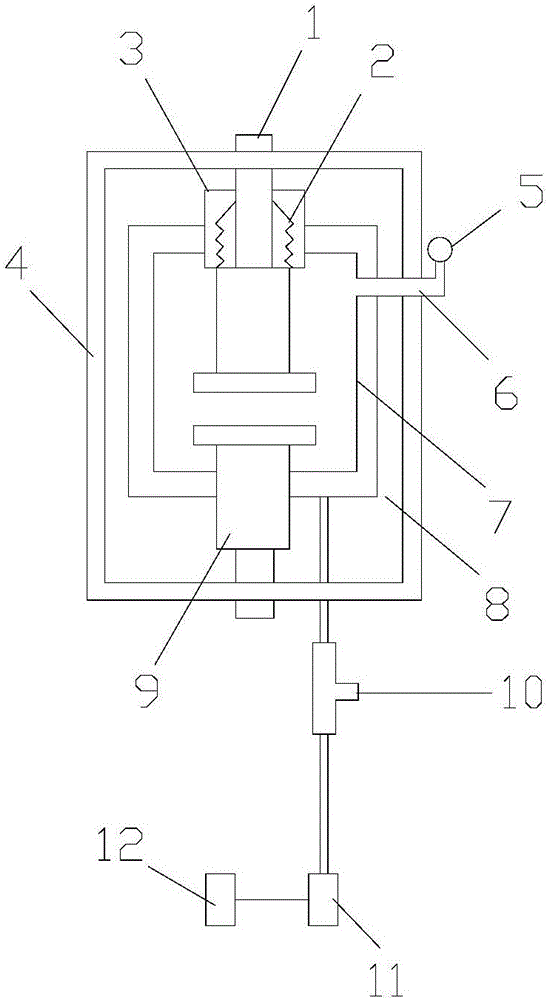
[0017] Referring to 1, a high-voltage circuit breaker includes an insulating case 4, a movable conductive rod 1, a fixed conductive rod 9, a first vacuum cover 8, a second vacuum cover 7, and a pressure measurement mechanism. The movable conductive rod 1 and the fixed conductive rod One end of the conductive rod 9 is respectively located in the first vacuum cover 7, and the other ends of the movable conductive rod 1 and the fixed conductive rod 9 respectively extend to the outside of the first vacuum cover 8, and the first vacuum cover 8 is also provided with a second Two vacuum covers 7, the side wall of the second vacuum cover 7 communicates with a glass tube 6, the glass tube 6 extends to the outside of the first vacuum cover 8, the end of the glass tube 6 is provided with a pressure measuring mechanism, the second An insulating shell 4 is arranged on the outside of a vacuum cover 8, and the second vacuum cover 7 is connected with a crank arm 10, and the crank arm 10 is conn...

Embodiment 2

[0026] Referring to 1, a high-voltage circuit breaker includes an insulating case 4, a movable conductive rod 1, a fixed conductive rod 9, a first vacuum cover 8, a second vacuum cover 7, and a pressure measurement mechanism. The movable conductive rod 1 and the fixed conductive rod One end of the conductive rod 9 is respectively located in the first vacuum cover 7, and the other ends of the movable conductive rod 1 and the fixed conductive rod 9 respectively extend to the outside of the first vacuum cover 8, and the first vacuum cover 8 is also provided with a second Two vacuum covers 7, the side wall of the second vacuum cover 7 communicates with a glass tube 6, the glass tube 6 extends to the outside of the first vacuum cover 8, the end of the glass tube 6 is provided with a pressure measuring mechanism, the first An insulating shell 4 is arranged on the outside of a vacuum cover 8, and the second vacuum cover 7 is connected with a crank arm 10, and the crank arm 10 is conne...

Embodiment 3

[0035] Referring to 1, a high-voltage circuit breaker includes an insulating case 4, a movable conductive rod 1, a fixed conductive rod 9, a first vacuum cover 8, a second vacuum cover 7, and a pressure measurement mechanism. The movable conductive rod 1 and the fixed conductive rod One end of the conductive rod 9 is respectively located in the first vacuum cover 7, and the other ends of the movable conductive rod 1 and the fixed conductive rod 9 respectively extend to the outside of the first vacuum cover 8, and the first vacuum cover 8 is also provided with a second Two vacuum covers 7, the side wall of the second vacuum cover 7 communicates with a glass tube 6, the glass tube 6 extends to the outside of the first vacuum cover 8, the end of the glass tube 6 is provided with a pressure measuring mechanism, the first An insulating shell 4 is arranged on the outside of a vacuum cover 8, and the second vacuum cover 7 is connected with a crank arm 10, and the crank arm 10 is conne...


PUM


Abstract

The invention discloses a high-voltage circuit breaker device, and the device comprises an insulating housing, a moving conductive rod, a fixed conductive rod, a first vacuum cover, a second vacuum cover and a pressure measurement mechanism. One end of the moving conductive rod and one end of the fixe conductive rod are respectively disposed in the first vacuum cover, and the other ends of the moving and fixed conductive rods respectively extend to the exterior of the first vacuum cover. The interior of the first vacuum cover is also provided with the second vacuum cover, and a side wall of the second vacuum cover is communicated with a glass tube. The glass tube extends to the exterior of the first vacuum cover. The tail end of the glass tube is provided with a pressure measurement mechanism, and the exterior of the first vacuum housing is provided with an insulating housing. The second vacuum housing is connected with a connecting lever, and the connecting lever is connected with a permanent magnet operating mechanism. The permanent magnet operating mechanism is connected with a power supply device, and the power supply device is a hand generator. The device can effectively maintain the high vacuum performance of an arc extinguish chamber, prevents the leakage, saves the cost, is good in flame retardation effect, and facilitates the turn-off of a circuit.

Description

technical field [0001] The invention specifically relates to a high-voltage circuit breaker. Background technique [0002] The high-voltage circuit breaker, also known as the vacuum switch tube, is the core component of the medium and high voltage power switch. Its main function is to quickly extinguish the arc and suppress the current after the medium and high voltage circuit is cut off through the excellent insulation of the vacuum in the tube, so as to avoid accidents and accidents. It is mainly used in the power transmission and distribution control system of electric power, and also used in power distribution systems such as metallurgy, mining, petroleum, chemical industry, railway, broadcasting, communication, and industrial high-frequency heating. It has the characteristics of energy saving, material saving, fire prevention, explosion protection, small size, long life, low maintenance cost, reliable operation and no pollution. The high-voltage circuit breaker is divi...

Claims


Application Information

Patent Timeline
Patent Type & Authority Applications(China)
IPC IPC(8): H01H33/662H01H33/664H01H33/666H01H33/668C08L83/07C08L1/28C08K13/02C08K5/20C08K3/34
CPCC08L83/04C08L2205/025C08L2205/035H01H33/662H01H33/664H01H33/666H01H33/668C08L1/284C08K13/02C08K5/20C08K3/34Y02P20/141
Inventor 李聪
Owner 李聪
Why Eureka
Try Eureka