Plane conjugate cam contour detecting and abrasive machining device

A technology of plane conjugation and grinding, which is used in metal processing equipment, grinding machine parts, grinding/polishing equipment, etc. It can solve problems such as high manufacturing and maintenance costs, reduced work efficiency, and cam surface damage.

Inactive Publication Date: 2013-06-19
CHANGZHOU INST OF TECH
View PDF18 Cites 7 Cited by
  • Summary
  • Abstract
  • Description
  • Claims
  • Application Information

AI Technical Summary

Problems solved by technology

When the above four detection devices or detection systems are working, the cam must be removed from the processing equipment first, and then the detection is carried out. If the detection fails, the cam needs to be put back into the processing equipment and repositioned to continue processing, resulting in work Efficiency is greatly reduced, and the objects of detection are all the outer contours of plane disc cams
[0007] Chinese patent documents CN101434053B (patent application No. 20081020397.4), CN101561250B (patent application No. 200910052043.3) and CN101259596A (patent application No. 200810023391.3) respectively disclose an "automatic positioning and online measurement method and device for cam noncircular grinding", "large Size cam non-circular grinding intelligent positioning and online measurement method" and "a kind of numerical control cam grinding machine", the first of the three documents described in the online measurement belongs to the contact measurement, the measurement accuracy is low, and the contact measurement process May cause damage to the machined cam surface and the measuring head is subject to wear
In the second document, the online measurement belongs to laser image measurement, the detection device is complicated, and the manufacturing and maintenance costs are high
The first two types of cam profile grinding devices and detection methods mentioned above are only used for the outer profile of flat disc cams
The third document is that it can only be processed, and the cam still needs to be removed from the equipment to be tested by another testing equipment.

Method used


Image

  • Plane conjugate cam contour detecting and abrasive machining device
  • Plane conjugate cam contour detecting and abrasive machining device
  • Plane conjugate cam contour detecting and abrasive machining device

Examples


Embodiment 1)

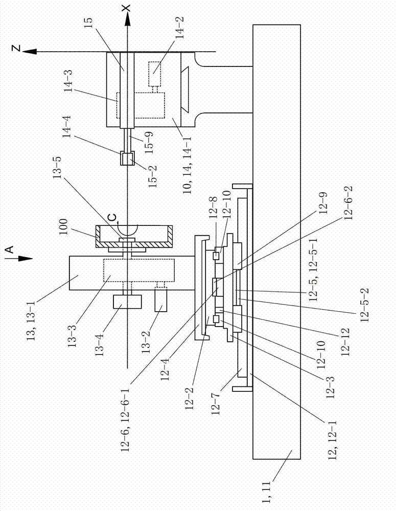
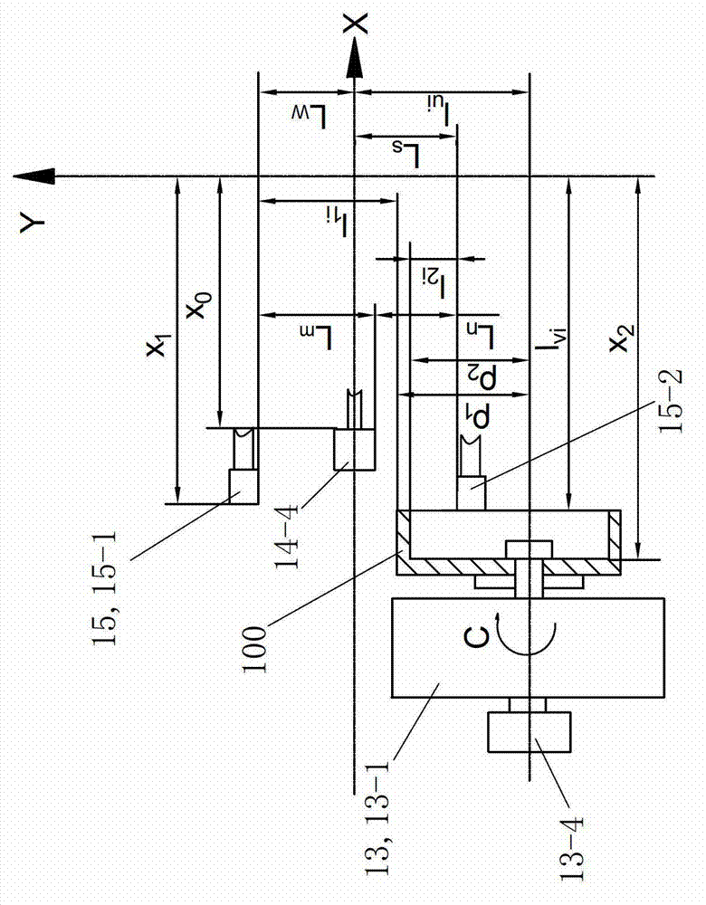
[0044] see figure 1 with figure 2 The planar conjugate cam profile detection and grinding processing device 1 of this embodiment includes a control system, a detection and grinding device 10, a body 11, a moving table mechanism 12 and a cam rotation mechanism 13. The movable table mechanism 12 is arranged on the fuselage 11 and can move relative to the fuselage 11 on the XY plane. The XY plane is a plane with any included angle with the horizontal plane (this embodiment is a horizontal plane, that is, the included angle with the horizontal plane is 0 degrees), and the movement is controlled by the control system. The cam rotation mechanism 13 is fixedly arranged on the table mechanism 12 and its action is controlled by a control system. The detection and grinding device 10 is fixedly arranged on the body 11 and its action is controlled by the control system.

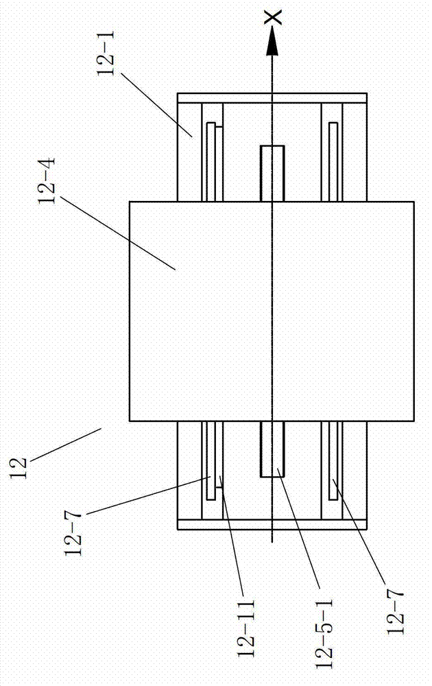
[0045] see figure 1 with figure 2 , The worktable mechanism 12 includes X-axis base 12-1, Y-axis base 12-2, connecting ...


PUM


Abstract

The invention discloses a plane conjugate cam contour detecting and abrasive machining device. When a grinding wheel head of a grinding mechanism of the detecting and abrasive machining device conducts abrasive machining to the outer contour of a plane conjugate cam, a second laser measuring head of a cam inner contour detecting device conducts reciprocating movement along the axial direction of the plane conjugate cam and measures a contour line in the axial direction of the inner contour of the plane conjugate cam. When the grinding wheel head of the grinding mechanism of the detecting and abrasive machining device conducts abrasive machining to the inner contour of the plane conjugate cam, a first laser measuring head of a cam outer contour detecting device conducts reciprocating movement along the axial direction of the plane conjugate cam and measures a contour line in the axial direction of the outer contour of the plane conjugate cam. When the cam rotates one cycle, the plane conjugate cam contour detecting and abrasive machining device can conduct on-line detection in the circumferential direction to the dimension of one of the inner contour and the outer contour of the plane conjugate cam, and meanwhile can grind the other contour of the inner contour and the outer contour of the plane conjugate cam.

Description

Technical field [0001] The invention relates to the field of mechanical manufacturing, in particular to a processing device for detecting and grinding the contour of a plane conjugate cam. Background technique [0002] The cam mechanism is a transmission mechanism mainly composed of a cam, a follower and a frame. Cams are usually divided into three types: disc cams, moving cams and cylindrical cams. Disc cams are divided into disc-shaped inner cams and disc-shaped outer cams. Because disc-shaped inner cams are rarely used, so-called disc-shaped cams generally refer to disc-shaped outer cams. According to the different trajectories of the follower, cams are divided into plane cams and space cams. Planar cam means that the movement plane of the cam is parallel to or coincides with the movement plane of the follower. Both disc cams and moving cams belong to plane cams. Space cams mean that the movement track of the follower is a space curve. Cylindrical cams belong to space cams. ...

Claims


Application Information

Patent Timeline
Patent Type & Authority Applications(China)
IPC IPC(8): B24B49/12B24B49/04
Inventor 郭建江张建生沈洪雷
Owner CHANGZHOU INST OF TECH
Why Eureka
Try Eureka