Disc cam contour detecting method

A disc cam and contour detection technology, which is applied to the parts of grinding machine tools, metal processing equipment, grinding/polishing equipment, etc., can solve the problems of easy wear of the measuring head, high manufacturing and maintenance costs, and low measurement accuracy. Improve measurement accuracy, processing accuracy and surface roughness level, improve work efficiency, and have a wide range of applications

Inactive Publication Date: 2015-04-29
CHANGZHOU INST OF TECH
View PDF18 Cites 0 Cited by
  • Summary
  • Abstract
  • Description
  • Claims
  • Application Information

AI Technical Summary

Problems solved by technology

Although the test in this document is an online automatic test, it also belongs to point detection when it works, and the measurement accuracy is still low
[0006] Chinese patent documents CN101434053B (patent application number 20081020397.4) and CN101561250B (patent application number 200910052043.3) respectively disclose a kind of "automatic positioning and on-line measurement method and device for cam noncircular grinding" and "intelligent search for large size cam noncircular grinding". Position and on-line measurement method”, said in the first article, the on-line measurement belongs to the contact measurement, the measurement accuracy is low, the surface of the processed cam may be damaged during the contact measurement process, and the measuring head is easy to wear
In the second document, the online measurement belongs to laser image measurement, the detection device is complicated, and the manufacturing and maintenance costs are high
Although the detection device of the plane conjugate cam involved in this document can measure the inner and outer contours of the plane conjugate cam at the same time, it belongs to contact measurement, and the measurement accuracy needs to be further improved.

Method used

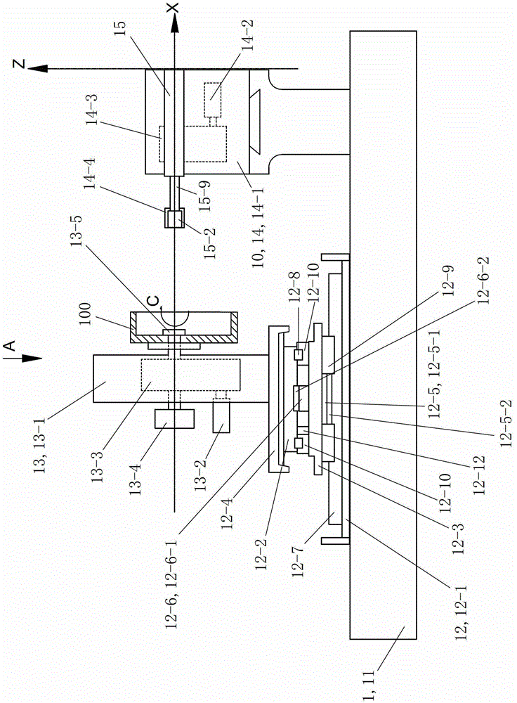

Image

  • Disc cam contour detecting method
  • Disc cam contour detecting method
  • Disc cam contour detecting method

Examples


Embodiment 1

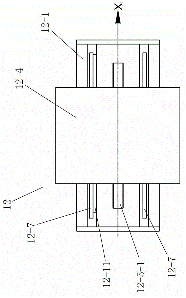
[0046] See figure 1 and figure 2, The cam processing detection device 1 of this embodiment includes a control system, a detection grinding device 10 , a body 11 , a moving table mechanism 12 and a cam rotation mechanism 13 . The mobile workbench mechanism 12 is arranged on the fuselage 11 and can move on the X-Y plane relative to the fuselage 11. The X-Y plane is a plane with any angle with the horizontal plane (the present embodiment is a horizontal plane, and the angle with the horizontal plane is 0 degrees), and the movement performed is controlled by the control system. The cam rotation mechanism 13 is fixedly arranged on the table mechanism 12 and its action is controlled by the control system. The detection grinding device 10 is fixedly arranged on the machine body 11 and its action is controlled by the control system.

[0047] See figure 1 and figure 2 , the table mechanism 12 includes an X-axis base 12-1, a Y-axis base 12-2, a connecting seat 12-3, a workbench 12...

Embodiment 2

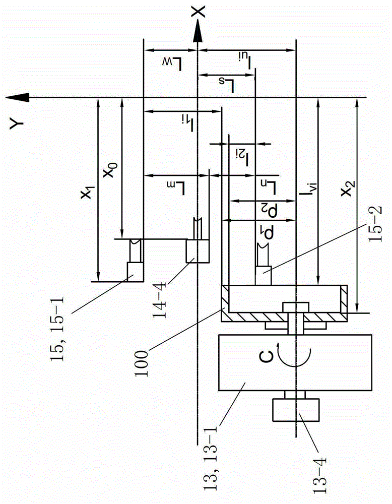
[0066] The remainder of this embodiment is the same as that of Embodiment 1, and the cam processing detection device 1 described in Embodiment 1 is still used. The linear motor driver 15-5 controls the mover 15-3-2 of the first linear motor 15-3 to drive the first laser measuring head 15-1 to move in the X direction to measure the outer contour size of the disc-shaped outer cam; the first laser The reference distance between the measuring head 15-1 and the axis of the grinding wheel grinding head 14-4 is L w , the rotation angle of the disc-shaped outer cam is θ i , the distance between the installation axis of the disc-shaped outer cam and the axis of the emery wheel grinding head 14-4 is l ui , the distance between the disc-shaped outer cam end face and the Y-axis of the grinding table 14-1 is l vi , the measured value of the distance between the outer contour of the disc-shaped outer cam measured online and the first laser measuring head 15-1 is l 1i , 0°≤θ i ≤360°, θ ...


PUM


Abstract

The invention discloses a disc cam contour detecting method which can be suitable for contour detection for different disc cams and particularly can be used for inner contour and outer contour detection for a plane conjugate cam. Cam processing and detecting equipment which is utilized comprises a control system, a machine body, a working platform mechanism, a cam rotation mechanism and a detection grinding device. The control system controls action of the working platform mechanism, the cam rotation mechanism and the detection grinding device. An on-line detecting device comprises a cam outer contour on-line detecting device and a cam inner contour on-line detecting device. The cam outer contour on-line detecting device is controlled by the control system through an actuator of a first linear motor, and an active cell of the first linear motor drives a first laser measuring head to carry out X-direction movement to measure the outer contour size of the plane conjugate cam. The cam inner contour on-line detecting device is controlled by the control system through an actuator of a second linear motor, and an active cell of the second linear motor drives a second laser measuring head to carry out X-direction movement to measure the inner contour size of the plane conjugate cam.

Description

technical field [0001] The invention relates to a method for detecting the profile of a disc cam. Background technique [0002] The cam mechanism is a transmission mechanism mainly composed of a cam, a follower and a frame. According to different forms, cams are usually divided into three types: disc cams, moving cams and cylindrical cams. Disc cams are further divided into disc-shaped inner cams and disc-shaped outer cams. Because disc-shaped inner cams are rarely used, the disc-shaped cams usually referred to as disc-shaped cams refer to disc-shaped outer cams. According to the difference of the movement trajectory of the follower, the cam is divided into a plane cam and a space cam. Plane cam means that the motion plane of the cam and the motion plane of the follower are parallel or coincident with each other. Disc cams and moving cams belong to plane cams, while space cams mean that the movement track of the follower is a space curve, and cylindrical cams belong to spa...

Claims


Application Information

Patent Timeline
Patent Type & Authority Patents(China)
IPC IPC(8): B24B49/04B24B49/12
Inventor 郭建江张建生沈洪雷庄志红
Owner CHANGZHOU INST OF TECH
Why Eureka
Try Eureka