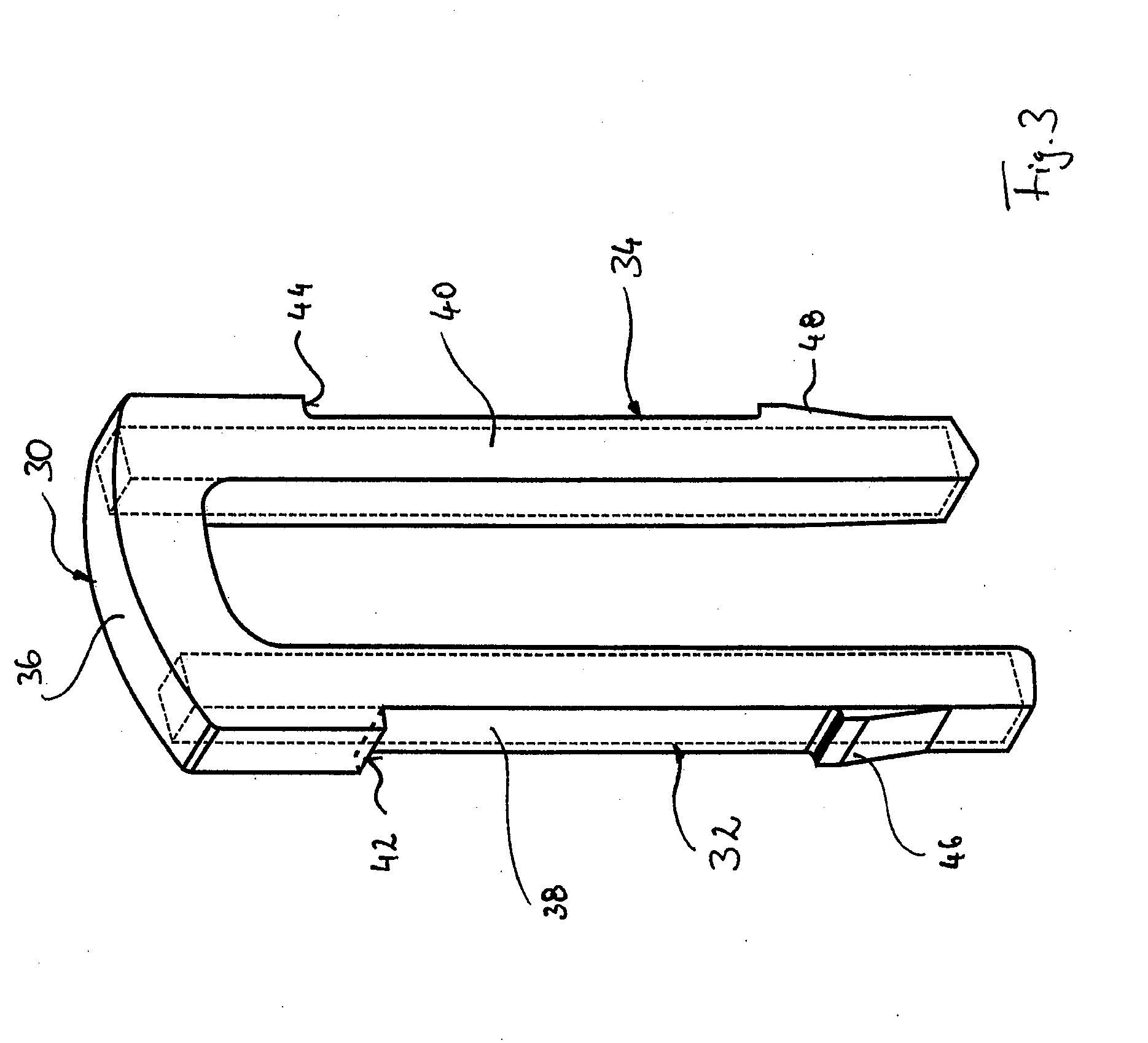
[0009]According to the invention, the travel limiting element is accordingly designed so that the load-bearing sections are reinforced by the reinforcement braces, that, however, these are already embedded in the transverse leg so that sufficient dimensional stability of the travel limiting element is achieved, with this at the same time being formed so as to be lighter and
noise-damping in the relevant areas.
[0010]The reinforcement braces can be designed according to requirements. Thus it is possible for the reinforcement braces to have a differing material thickness. The particular
advantage of using rectilinear reinforcement braces lies in the fact that—other than in the case of the prior art—no special shaping by
stamping or forming is required. Instead, according to one development of the invention, reinforcement braces of
metal, in particular of drawn longitudinal steel or wire material can be used, in which case no special requirements have to be met by the surface quality of the material. It is alternatively possible for the reinforcement braces to consist of plastics material, in particular of tough or fibre-reinforced or body-reinforced plastics material. It is thus possible to produce the travel limiting element from sufficiently tough plastics material and to achieve a significant weight saving when compared with conventional metallic travel limiting elements according to the prior art.
[0011]It is also possible according to the invention for the damping material to be constituted by a partially elastic or an elastomeric plastics material. When selecting the damping material, particular attention should be paid to preventing the occurrence of undesirable noises in consequence of the stop action. According to one constructional variant, the damping material can be fibre-reinforced or body-reinforced. The stability of the travel limiting element according to the invention is further increased as a result. The
toughness thereof can also be increased by adding suitable chemical additives.
[0012]According to one advantageous embodiment of the invention, the reinforcement braces are completely embedded in the damping material. In this connection the
advantage of the low requirements to be met by the surface quality of the reinforcement braces, which is relevant in terms of the production costs, is again to be emphasised. By completely embedding the reinforcement braces in the damping material, it is also possible to use reinforcement braces of cost-effective longitudinal steel, for example with a square profile, which have an untreated surface and are therefore particularly cost-effective in terms of acquisition.
[0013]A further
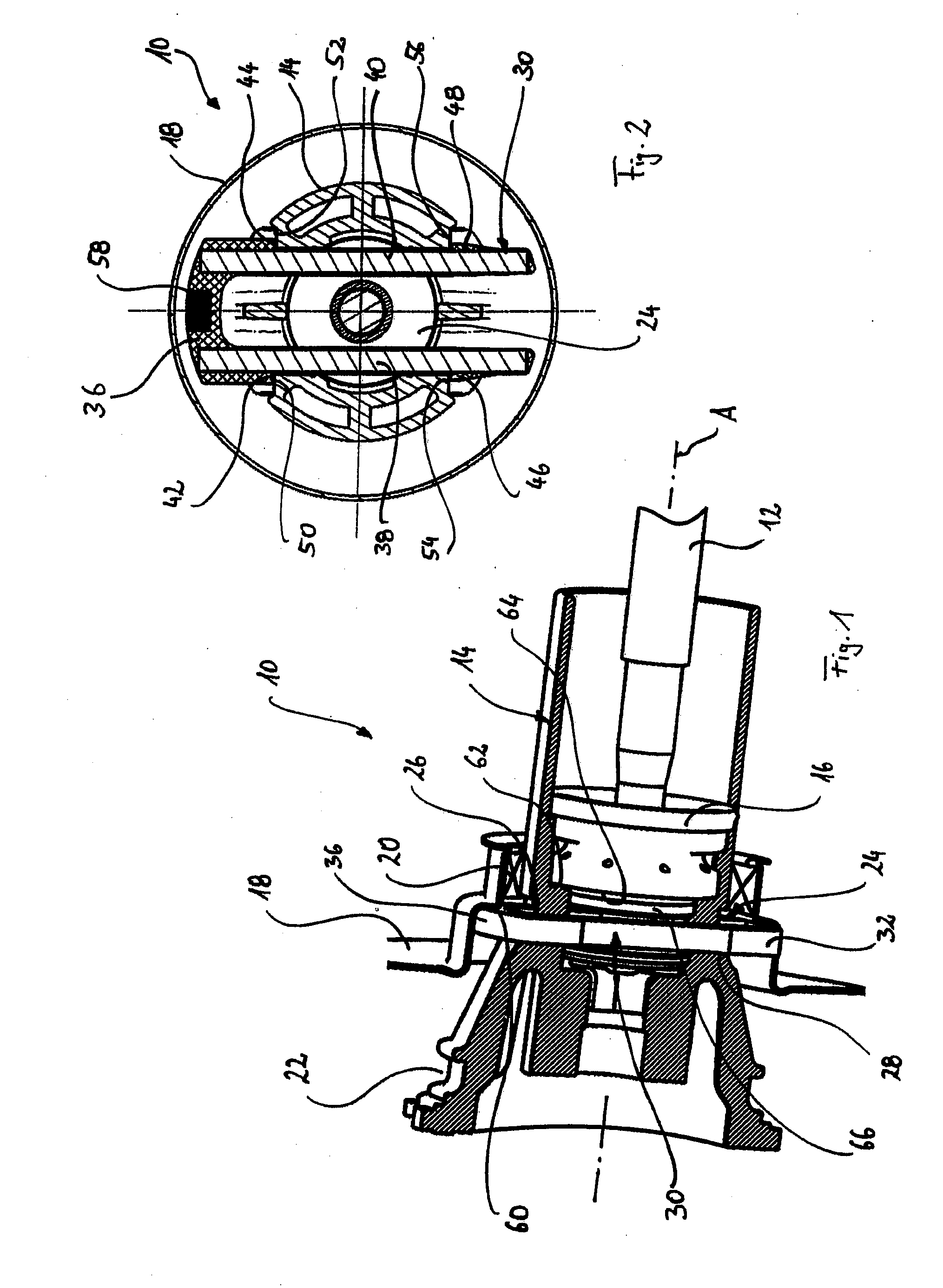
advantage of the “built-up” construction of the travel limiting element according to the invention lies in the fact that a component of a displacement sensor, in particular a
magnet of a Hall sensor, can be embedded in the transverse leg, which can be made of the elastomeric material, for example by
injection moulding or similar. In this variant of the invention the displacement sensor component can advantageously be coupled to the transmission
piston device in a space-saving and at the same time protected manner, so that any movement of the transmission
piston device and therefore of the force input member can be detected. Additional
magnet holders or similar, as are known to the person skilled in the art from the prior art, can therefore be avoided, which further simplifies the production as well as the design of the brake booster.
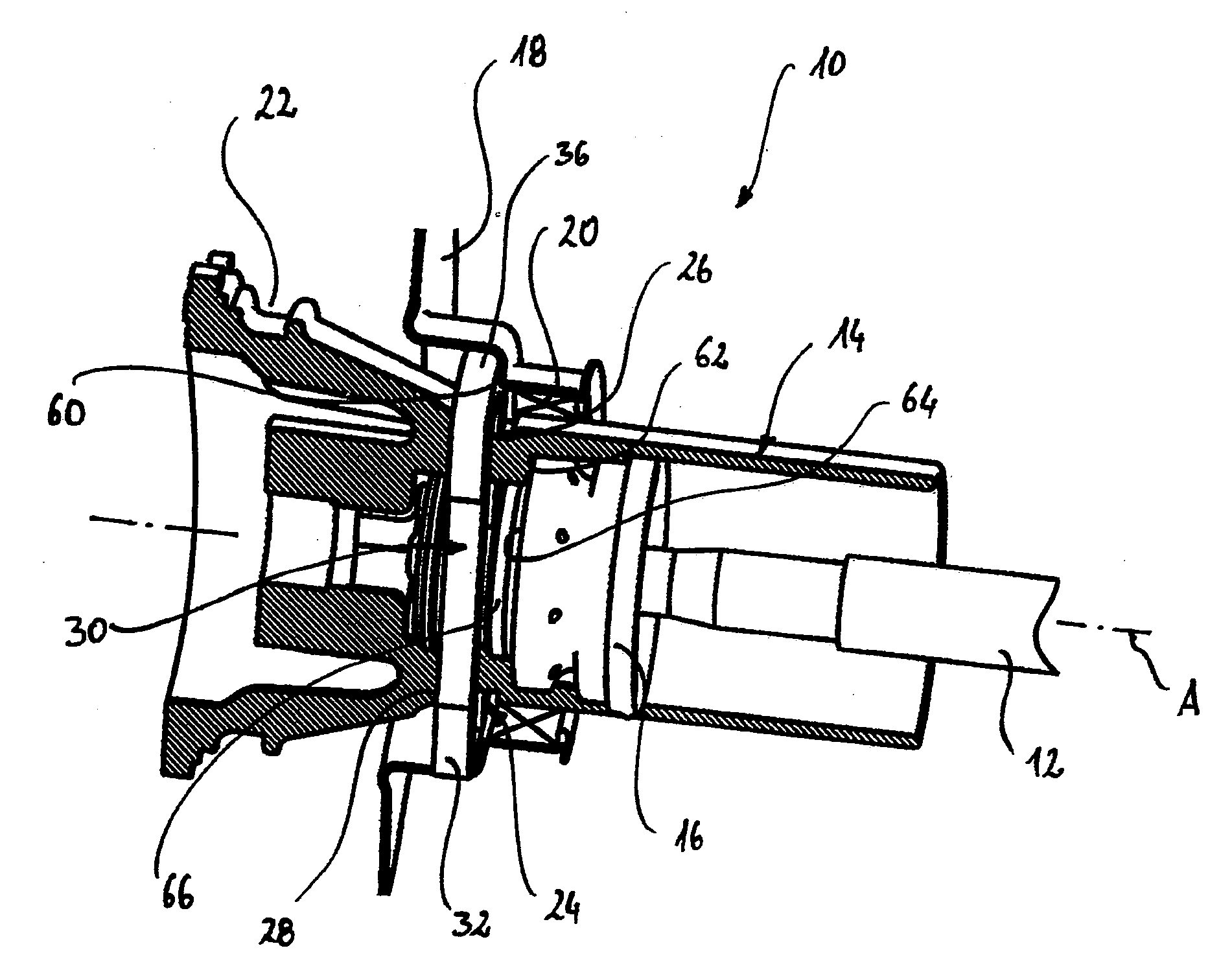
[0014]The travel limiting element is usually inserted from above in an opening in the control valve housing when
assembly takes place. According to one development of the invention, in order to simplify this process and to clearly define the
assembly position of the travel limiting element according to the invention, at least one stop formation is provided on or near the transverse leg and at least one locking tooth formation is provided on the longitudinal legs. The stop formation serves to position the travel limiting element in a defined position transversely to the longitudinal direction of the brake booster device. In this defined position the at least one locking tooth formation then locks with a corresponding
mating locking tooth formation, for example on the control valve housing, so that there is no possibility of the travel limiting element inadvertently coming loose. In this connection it is preferable for the stop formation and / or the locking tooth formation to be made of the damping material and moulded onto the transverse leg as well as onto the longitudinal legs. This also enables the production of the travel limiting element according to the invention to be simplified, as the stop formation and / or the locking tooth formation can be subsequently formed by moulding onto the connecting braces. In the prior art corresponding formations are constituted by material sections obtained through the
stamping process or through
forming processes.

