Metal-clad laminate and manufacturing method of the same

a metal-clad laminate and manufacturing method technology, applied in metal-clad products, film/foil adhesives without carriers, domestic applications, etc., can solve the problems of poor reliability of metal-clad laminates using fluoropolymer metal-clad laminates, poor dimensional stability of metal-clad laminates with fluoropolymer as the dielectric material at different temperatures, and failure to meet the requirements of conventional epoxy resin dielectric materials, etc., to achieve efficient reduction of filling

Pending Publication Date: 2020-12-24
TAIWAN POWDER TECH CO LTD
View PDF1 Cites 3 Cited by
  • Summary
  • Abstract
  • Description
  • Claims
  • Application Information

AI Technical Summary

Benefits of technology

[0007]In view of the abovementioned technical problems, the present invention provides a metal-clad laminate that not only uses a fluoropolymer adhesive layer with a lower melting point to improve the adhesion between the dielectric layer and the metal foil but also introduces a specific ratio of filler into the adhesive layer of the laminate to efficiently reduce the amount of filler used in the core dielectric layer. The present invention addresses the following shortcomings of the prior art: the overly-high viscosity of the composition and the resulting uneven thickness of the fluoropolymer and poor reliability, wherein the aforementioned shortcomings are caused by adding a large amount of filler in the core dielectric layer for the purpose of achieving sufficient dimensional stability.

Problems solved by technology

However, the characteristics of conventional epoxy resin dielectric materials have failed to keep up with the requirements, and thus, conventional dielectric materials used for metal-clad laminates are being replaced with fluoropolymers, such as polytetrafluoroethylene (PTFE).
However, a metal-clad laminate with fluoropolymer as the dielectric material has poor dimensional stability at different temperatures, especially for the coefficient of thermal expansion in the thickness direction of the substrate (Z-axis), hereinafter also referred to as “Z-CTE,” which is usually more than 100 ppm / ° C. As a result, products using fluoropolymer metal-clad laminates have poor reliability.
However, adding a large amount of filler to the fluoropolymer will result in a rapid increase in the viscosity of the composition.
Therefore, when a reinforcing material is impregnated with the composition in the follow-up process, the composition cannot be distributed evenly on the reinforcing material, and the wetting of the composition to the reinforcing material becomes poor.
In addition, the fluoropolymer metal-clad laminate generally has insufficient peeling strength since the adhesion between the fluoropolymer and the metal foil of the laminate is generally poor.
When a “low profile” metal foil is used in a laminate to meet the requirements for electrical properties (such as pursuing a lower dielectric dissipation), the anchor effect between the fluoropolymer and the metal foil is particularly insufficient.
The bonding surface (bonding site) of the metal foil and the fluoropolymer dielectric layer is not subjected to a roughening process, and therefore, the prepared laminate has an even worse peeling strength.
However, while the method of using a fluoropolymer thin film as an adhesive layer overcomes the problem of insufficient adhesion between the metal foil and the fluoropolymer dielectric layer, it does not solve the problem of the overly-high viscosity of the composition and non-even coating caused by adding a large amount of filler for the purpose of meeting the dimensional stability requirement.

Method used


Image

  • Metal-clad laminate and manufacturing method of the same

Examples


example 1

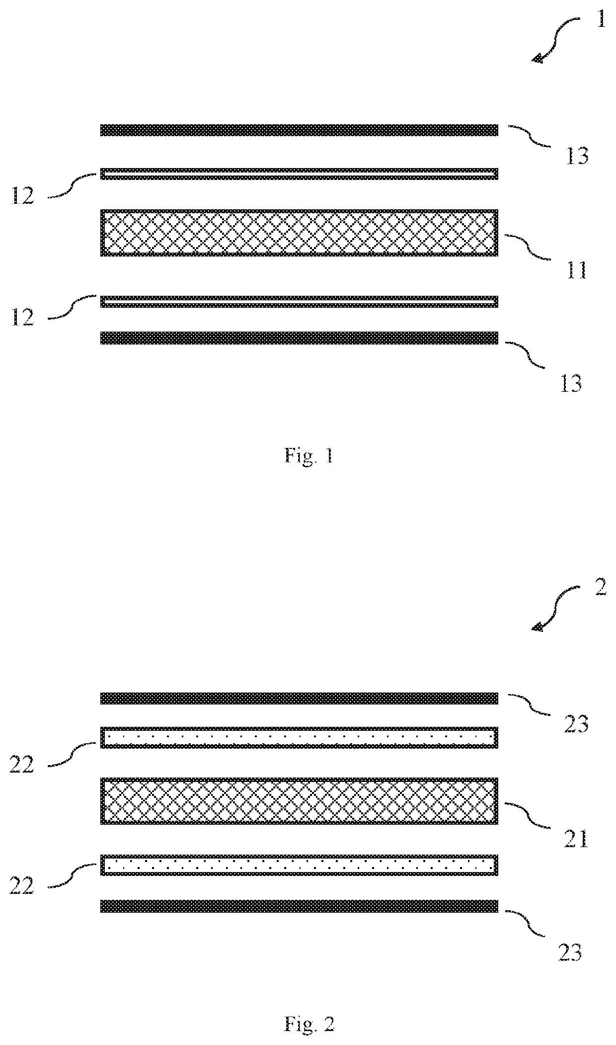
[0079]1000 grams of PTFE dispersion (the solid content of PTFE being 60 wt %) and 400 grams of the filler were mixed evenly to form a varnish of dielectric material (i.e., based on the solid content of the varnish, the amount of filler being 40 wt %). A 1080-type E-glass fabric was impregnated with the varnish, and was subjected to baking at 360° C. to obtain a PTFE prepreg. In addition, 1170 grams of PFA dispersion (the solid content of PFA being 60 wt %) and 300 grams of the filler were mixed evenly to form a varnish of adhesive material (i.e., based on the solid content of the varnish, the amount of filler being 30 wt %). After that, a 1067-type E-glass fabric was impregnated with the varnish, and was subjected to baking at 330° C. to obtain a PFA prepreg containing a filler. Then, 4 sheets of the PTFE prepreg obtained above were first stacked (as the dielectric layer), and then 1 sheet of the PFA prepreg obtained above (as the adhesive layer) was attached to each of the upper an...

example 2

[0080]1000 grams of PTFE dispersion (the solid content of PTFE being 60 wt %) and 400 grams of the filler were mixed evenly to form a varnish of dielectric material (i.e., based on the solid content of the varnish, the amount of filler being 40 wt %). A 1080-type E-glass fabric was then impregnated with the varnish, and was subjected to baking at 360° C. to obtain a PTFE prepreg. In addition, 1000 grams of PFA dispersion (the solid content of PFA being 60 wt %) and 400 grams of the filler were mixed evenly to form a varnish of adhesive material (i.e., based on the solid content of the varnish, the amount of filler being 40 wt %). After that, the varnish was coated on the shiny side of a copper foil by using a scraper, subjected to baking at 330° C., and then stripped off to obtain a filler-containing PFA film. Then, 4 sheets of the PTFE prepreg obtained above were first stacked (as the dielectric layer), and then 1 sheet of the filler-containing PFA film obtained above (as the adhes...


PUM

PropertyMeasurementUnit
surface roughnessaaaaaaaaaa
melting pointaaaaaaaaaa

Abstract

A metal-clad laminate is provided. The metal-clad laminate includes:
    • a dielectric layer, which has a first reinforcing material and a dielectric material formed on the surface of the first reinforcing material, wherein the dielectric material includes 60 wt % to 80 wt % of a first fluoropolymer and 20 wt % to 40 wt % of a first filler;
    • an adhesive layer, which is disposed on at least one side of the dielectric layer and includes an adhesive material, wherein the adhesive material has 60 wt % to 70 wt % of a second fluoropolymer and 30 wt % to 40 wt % of a second filler; and
    • a metal foil, which is disposed on the other side of the adhesive layer that is opposite to the dielectric layer,
    • wherein the melting point of the second fluoropolymer is lower than the melting point of the first fluoropolymer.

Description

CLAIM FOR PRIORITY[0001]This application claims the benefit of Taiwan Patent Application No. 108121826 filed on Jun. 21, 2019, the subject matters of which are incorporated herein in their entirety by reference.BACKGROUNDField of the Invention[0002]The present invention provides a metal-clad laminate, especially, a fluoropolymer metal-clad laminate, and a manufacturing method of the same. The fluoropolymer metal-clad laminate of the present invention is particularly suitable for use as a circuit substrate in high-frequency technical fields, including radio frequency (RF) applications, microwave applications, mm wave applications, antenna applications, radar applications, and the like. In particular, the fluoropolymer metal-clad laminate of the present invention can meet the need for high-level materials in advanced applications, such as 5th generation mobile networks (5G), advanced driver assistance systems (ADAS), and artificial intelligence (AI).Descriptions of the Related Art[000...

Claims


Application Information

Patent Timeline
Patent Type & Authority Applications(United States)
IPC IPC(8): H05K1/03H05K3/02
CPCH05K3/022H05K2201/0195H05K2201/015H05K2201/0293H05K1/036H05K2201/029B32B7/12B32B15/14B32B5/26B32B37/06B32B37/10C09J127/18C09J11/04C09J7/10B32B2260/021B32B2262/101B32B2262/0253B32B2262/0276B32B2307/204B32B2457/08C08K3/36H05K2201/068H05K2201/026H05K2201/0323H05K2201/0209H05K2201/0212H05K2201/0248H05K1/0366H05K1/0373
Inventor CHEN, WEN-RENHUANG, SHI-INGLIU, SHUR-FEN
Owner TAIWAN POWDER TECH CO LTD
Why Eureka
Try Eureka