Shield structure and wiring harness

Pending Publication Date: 2022-05-05
AUTONETWORKS TECH LTD +2
View PDF0 Cites 0 Cited by
  • Summary
  • Abstract
  • Description
  • Claims
  • Application Information

AI Technical Summary

Benefits of technology

[0009]According to the present disclosure, at least one of effects of structure simplification, weight saving

Problems solved by technology

In the conventional art, the two wires disposed side by side are covered in a vertical direction and a lateral direction by a shield member made of metal due to a concern that noise is mixed from a part where the two wi

Method used


Image

  • Shield structure and wiring harness
  • Shield structure and wiring harness
  • Shield structure and wiring harness

Examples


Example

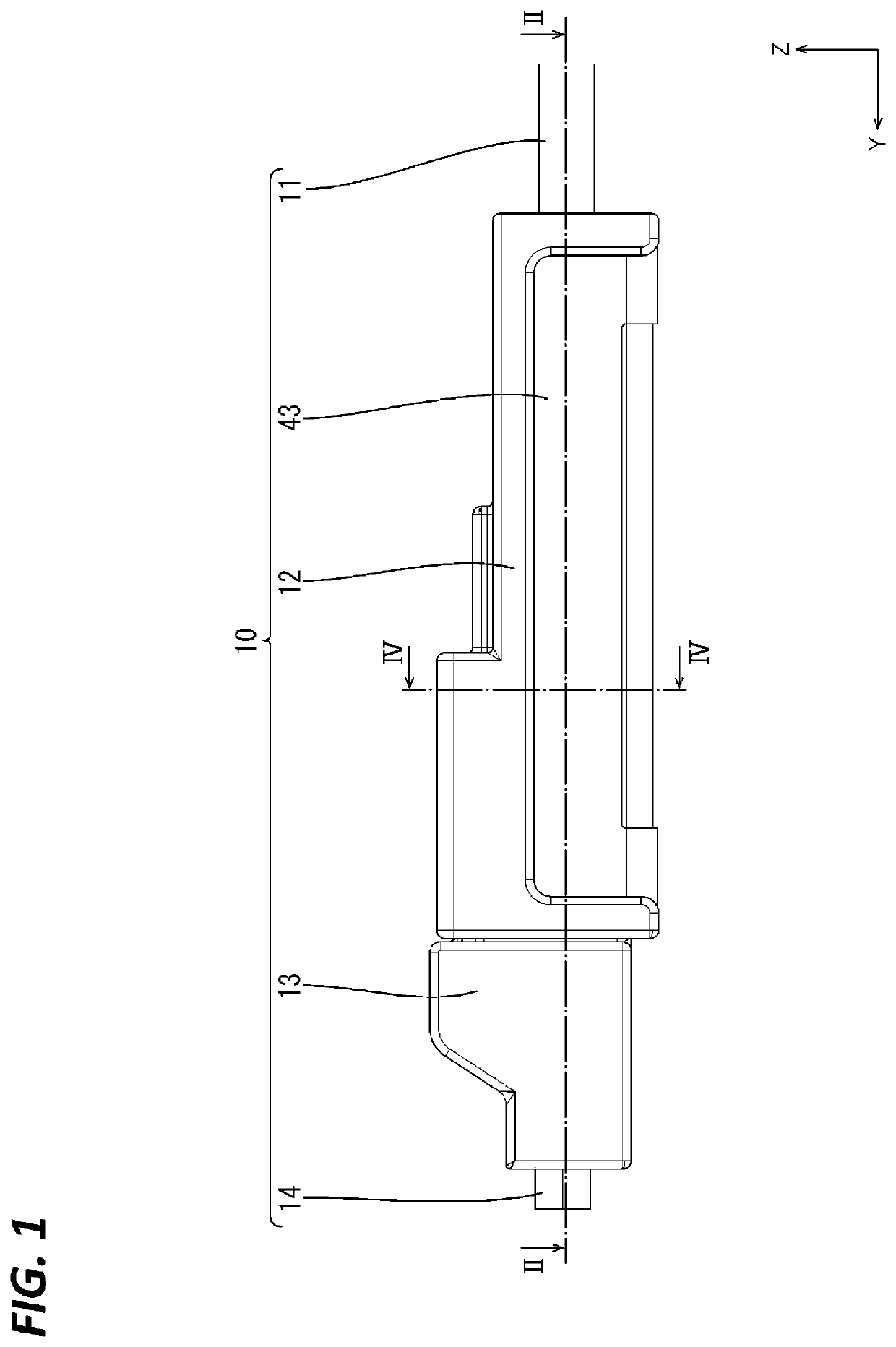
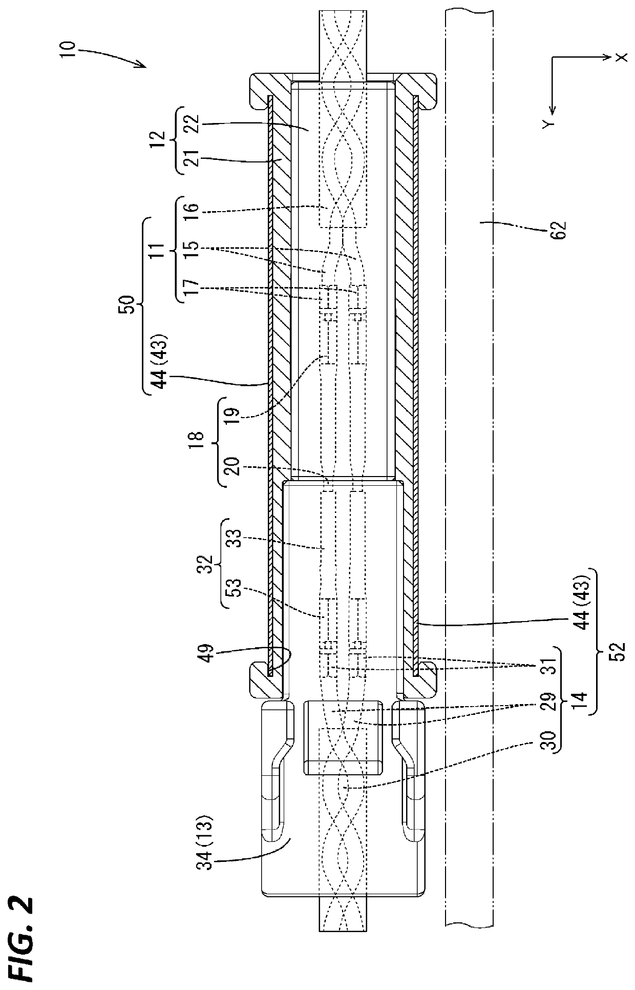
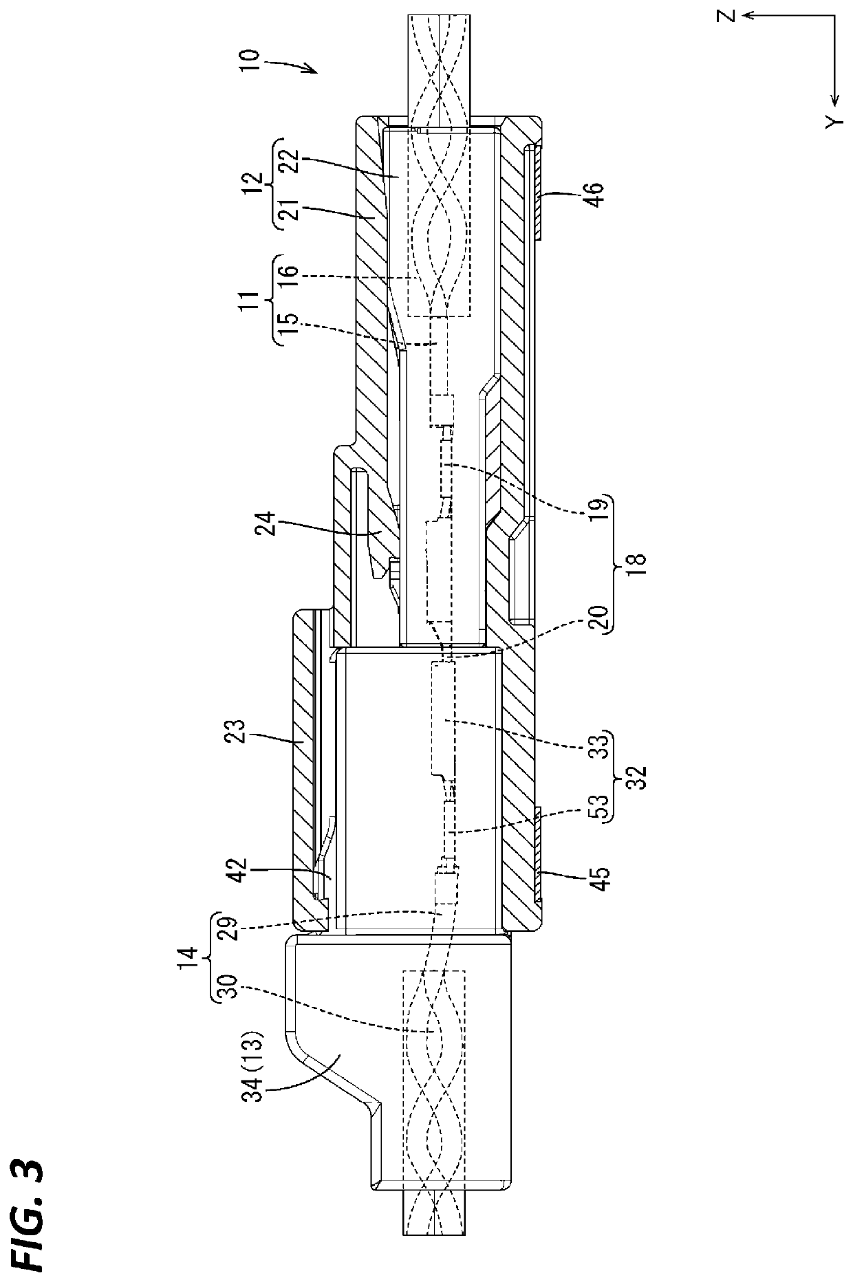
[0049]A first embodiment in which a technique disclosed in this specification is applied to a wiring harness 10 is described with reference to FIGS. 1 to 17. As shown in FIG. 1, the wiring harness 10 according to this embodiment includes a first UTP (Unshielded Twisted Pair) cable 11 (an example of a twisted pair cable), a male connector 12 (an example of a connector) connected to an end part of the first UTP cable 11, a female connector 13 (an example of the connector) to be connected to the male connector 12 and a second UTP (Unshielded Twisted Pair) cable 14 (an example of the twisted pair cable) having the female connector 13 connected to an end part.

[0050]A wire 62 serving as a noise source is fixed to the wiring harness 10 according to this embodiment by a known method such as taping while being disposed along the wiring harness 10 (see FIG. 4). A power supply wire connected to a device is illustrated as the wire 62 serving as the noise source. Noise may be mixed into such a p...

Example

[0106]For the technique disclosed in this specification, Calculation Example 2 is an embodiment and Calculation Example 1 and Calculation Example 3 are comparative examples.

Example

Calculation Example 1

[0107]As shown in FIGS. 7A and 7B, the lower edges of two side wall portions 44 are electrically connected by a connecting portion 61 integrally formed to the two side wall portions 44 in a shield member 60 used in Calculation Example 1. The connecting portion 61 in Calculation Example 1 is not open in the vertical direction. Other components are similar to those of the first embodiment.

Calculation Example 2

[0108]As shown in FIGS. 6 and 8, the shield member 43 disclosed in the first embodiment was used in Calculation Example 2.


PUM


Abstract

A shield structure includes a twisted pair cable formed by twisting two wires and including a parallel portion, the two wires being arranged side by side in the parallel portion, and a shield member including two conductive side wall portions disposed around the parallel portion and two connecting portions configured to connect the two side wall portions. The two connecting portions are respectively disposed on front end parts and rear end parts in an extending direction of the parallel portion, out of the two side wall portions.

Description

TECHNICAL FIELD[0001]The present disclosure relates to a shield structure and a wiring harness.BACKGROUND[0002]Conventionally, a twisted pair cable formed by twisting two wires is known (Japanese Patent Laid-Open Publication No. 2012-018898). The twisted two wires are untwisted in an end part of the twisted pair cable, and the two wires are disposed side by side.PRIOR ART DOCUMENTPatent Document[0003]Patent Document 1: JP 2012-018898 ASUMMARY OF THE INVENTIONProblems to be Solved[0004]In the conventional art, the two wires disposed side by side are covered in a vertical direction and a lateral direction by a shield member made of metal due to a concern that noise is mixed from a part where the two wires are disposed side by side.[0005]Since the above shield member covers the two wires disposed side by side in the vertical and lateral directions, the structure thereof tends to be complicated and weight saving is difficult.[0006]The present disclosure was completed on the basis of the...

Claims


Application Information

Patent Timeline
IPC IPC(8): H01R13/6581H01R13/6591H01B7/00
CPCH01R13/6581H01B7/0045H01R13/6591H01R13/65915H01R2103/00
Inventor TAKAHASHI, KEIGOTAKAGI, HIROKISAKAI, MASAMI
Owner AUTONETWORKS TECH LTD
Why Eureka
Try Eureka