Core rod for forming a cylindrical green compact, apparatus for forming a cylindrical green compact, and method for forming a cylindrical green compact

Inactive Publication Date: 2008-10-30
KOBAYASHI KINYA +6
View PDF4 Cites 4 Cited by
  • Summary
  • Abstract
  • Description
  • Claims
  • Application Information

AI Technical Summary

Benefits of technology

[0026]For this reason, even when the corner between the upper surface of the step portion and the core rod side surface linked to the upper surface is not curved or its curvature radius is small, stress concentrated on the corner can be reduced.
[0027]In add

Problems solved by technology

The following problems arise when a method for green compact is used to manufacture doughnut-shaped or cylindrical green compact that have a protrusion in the axial direction or a step portion or dent portion in a radial direction on the inner surface.
First, since minimum widths of the punches are fixed, it is difficult

Method used


Image

  • Core rod for forming a cylindrical green compact, apparatus for forming a cylindrical green compact, and method for forming a cylindrical green compact
  • Core rod for forming a cylindrical green compact, apparatus for forming a cylindrical green compact, and method for forming a cylindrical green compact
  • Core rod for forming a cylindrical green compact, apparatus for forming a cylindrical green compact, and method for forming a cylindrical green compact

Examples


Example

First Embodiment

[0058]A first embodiment of the present invention will be described below with reference to FIGS. 5A to 5C, 6, 7, and 8A and 8B.

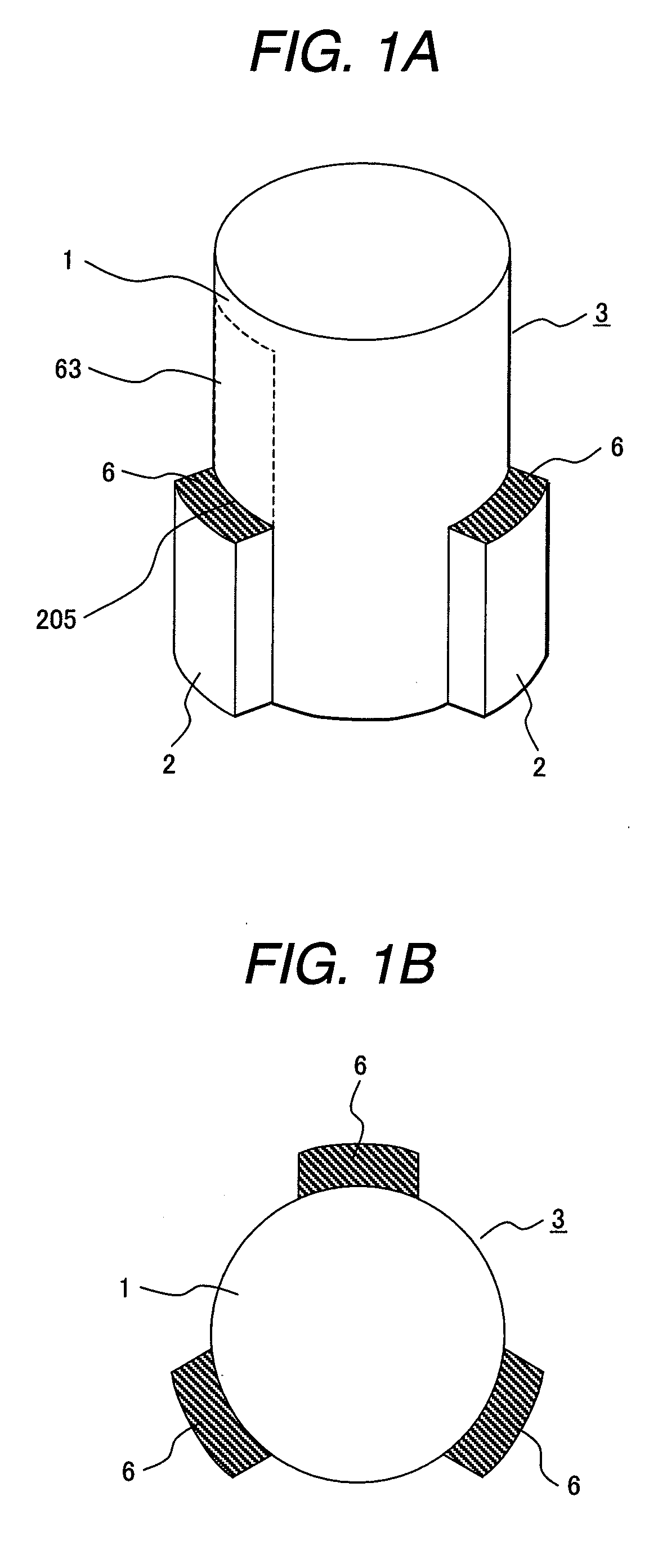
[0059]FIGS. 5A to 5C show the structure of the stepped core rod 3. FIG. 5A is a perspective view in a state in which the upper core 31 and lower core 32 are joined. FIG. 5B is a perspective view when the upper core 31 and lower core 32 are separated. FIG. 5C is a plan view viewed from above.

[0060]The stepped core rod 3 has three step portions 2 spaced in the peripheral direction, each of which has a convex protruding in a radial direction. The stepped core rod 3 is horizontally divided into two parts, an upper core 31 and a lower core 32, on a plane flush with the step's upper surface 6. The cross section 5 of the stepped core rod 3 is joined with the step's upper surface 6, their surfaces being flush with each other.

[0061]The upper core 31 and lower core 32 are joined on the cross section 5 in a manner in which they can be separated. In FIG...

Example

Second Embodiment

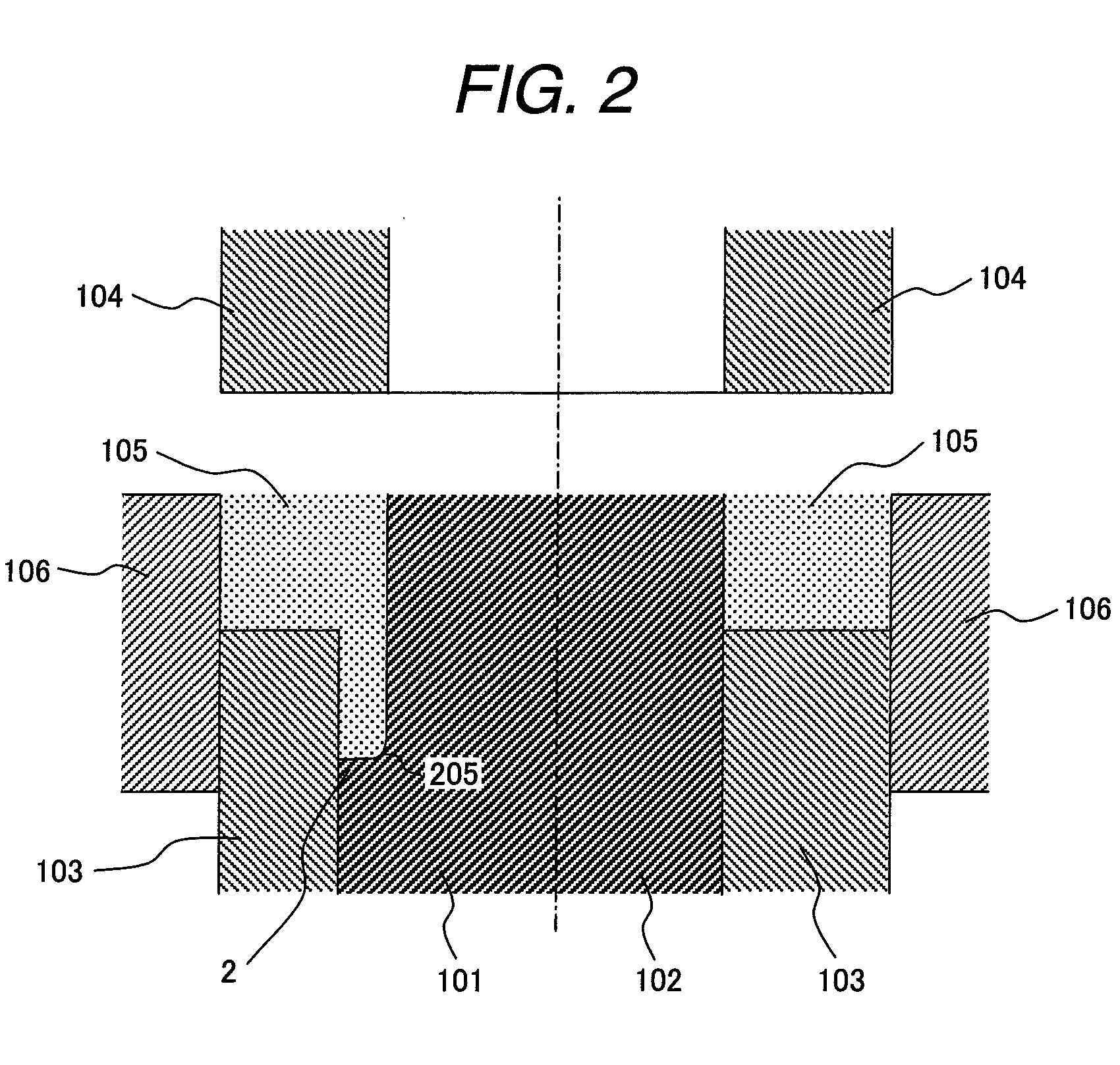
[0090]A second embodiment in which a green compact with dent portions is formed will be described with reference to FIGS. 9A, 9B, 10A, and 10B. FIGS. 9A and 9B respectively show the powder compaction apparatus before and after compacting is performed.

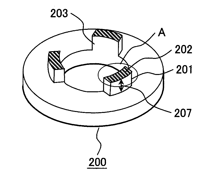
[0091]A powder compaction apparatus structured as in the first embodiment can be used to form a cylindrical or ring-shaped green compact 300 having dent portions 301 on the inner surface. As shown in FIGS. 9A and 9B, however, the lower punch 103 is disposed below the upper surface of the step portion 2 of the stepped core rod 3.

[0092]A load is applied by a press so that the entire density of the green compact 300 becomes 92% or more of the true density of the material constituting the powder, as in the first embodiment.

[0093]With the powder compaction apparatus structured as in FIGS. 9A and 9B, a green compact 300 having three dent structures 301 on the lower surface of the ring-shaped structure in the peripheral direct...

Example

[0116]A third embodiment in which a core rod 3 having a cylindrical step portion 20 is used will be described with reference to FIGS. 11A, 11B, 12, and 13.

[0117]The stepped core rod 3 shown in FIGS. 11A and 11B has a cylindrical step portion 20. The core rod 3 is horizontally divided into two parts, an upper core 31 and a lower core 32, on a plane flush with the step's upper surface 6 of the cylindrical step portion 20. The upper core 31 and lower core 32 are joined with a bolt 401 and a nut 402 on the plane along which the core rod 3 is divided. Shot peening is applied to the step's upper surface 6 of the lower core 32, the cross section 5, which is the dividing surface, and the outer surface of the upper core 31 so as to provide compressed residual stress.

[0118]FIG. 12 shows the structure of the powder compaction apparatus in a state after powder compaction is performed. The corner at the stepped structure of the cylindrical step portion 20 is not curvature.

[0119]The lower punch 1...


PUM

PropertyMeasurementUnit
Fractionaaaaaaaaaa
Fractionaaaaaaaaaa
Radiusaaaaaaaaaa

Abstract

A core rod for forming a cylindrical green compact having an axial protrusion or a radial step portion or dent portion on an inner surface of the cylindrical member by powder compaction, wherein: the core rod is provided with a step portion protruding in a radial direction at least a part on an outer surface thereof; the core rod is divided into two parts, an upper core and a lower core, on a plane that is flush with an upper surface of the step portion; and the upper core and lower core are mechanically joined with fastening members or bonded with an adhesive on a plane along which the core rod is divided.

Description

CLAIM OF PRIORITY[0001]The present application claims priority from Japanese application serial No. 2007-119661, filed on Apr. 27, 2007, the content of which is hereby incorporated by reference into this application.BACKGROUND OF THE INVENTION[0002]1. Field of the Invention[0003]The present invention relates to a core rod for forming a cylindrical green compact as well as an apparatus equipped with the core rod for forming a cylindrical green compact and a method for forming a cylindrical green compact. Cylindrical green compact referred to in this description have concentric inner and outer surfaces. Ring-shaped members having a height smaller than an outer diameter thereof are also considered as cylindrical green compact.[0004]2. Description of Related Art[0005]To manufacture a cylindrical green compact by powder compaction, a core rod, lower punch, upper punch, and die are usually used as described in, for example, Patent Document 1. In the method in Patent Document 1, powder is ...

Claims


Application Information

Patent Timeline
IPC IPC(8): B22F3/02B28B17/00
CPCB22F3/03B28B3/08B28B3/083B30B11/02
Inventor KOBAYASHI, KINYANAGASHIMA, HIDEAKIISHIZAWA, SHUUICHIENOMOTO, YUJIARAKAWA, TOMOAKISHIMA, JIROISHIHARA, CHIO
Owner KOBAYASHI KINYA
Why Eureka
Try Eureka