Blade driving device

a driving device and blade technology, applied in the direction of shutters, instruments, exposure control, etc., can solve the problems of large installation area, large actuator size, and inconvenient use, so as to reduce the thickness increase the size of the actuator, and facilitate the installation of the blade driving device.

Active Publication Date: 2018-02-08
COPAL CO LTD
View PDF6 Cites 4 Cited by
  • Summary
  • Abstract
  • Description
  • Claims
  • Application Information

AI Technical Summary

Benefits of technology

[0005]In a conventional blade driving device, in order to achieve a large movement in a blade member through a small driving stroke for the dislocation by the actuator, rotating member (a rotating arm) is used, where the point of force of the actuator is located near to the rotary shaft, and the operating point, for operating the blade member, is positioned at the tip end portion of the rotating member, away from the rotary shaft. In this way, the blade driving device that is equipped with such a rotating member requires an actuator that produces a large amount of torque through driving the rotating member near the rotary shaft, increasing the size of the actuator, making it difficult to reduce the thickness of the blade driving device.

Problems solved by technology

In this way, the blade driving device that is equipped with such a rotating member requires an actuator that produces a large amount of torque through driving the rotating member near the rotary shaft, increasing the size of the actuator, making it difficult to reduce the thickness of the blade driving device.
Because the blade member is operated through a relatively long rotating member, the driving members, such as the magnet, and the like, that structure the actuator are provided at positions that are separated from the blade member, and thus there is a problem in that the area for installing the blade driving device, which includes the driving member, of necessity, must be large when compared to the opening.

Method used


Image

  • Blade driving device
  • Blade driving device
  • Blade driving device

Examples


Embodiment Construction

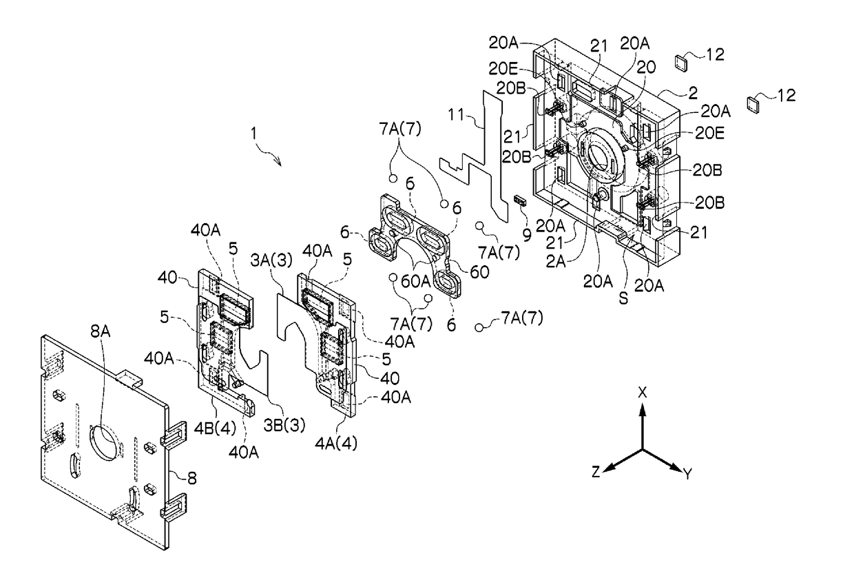
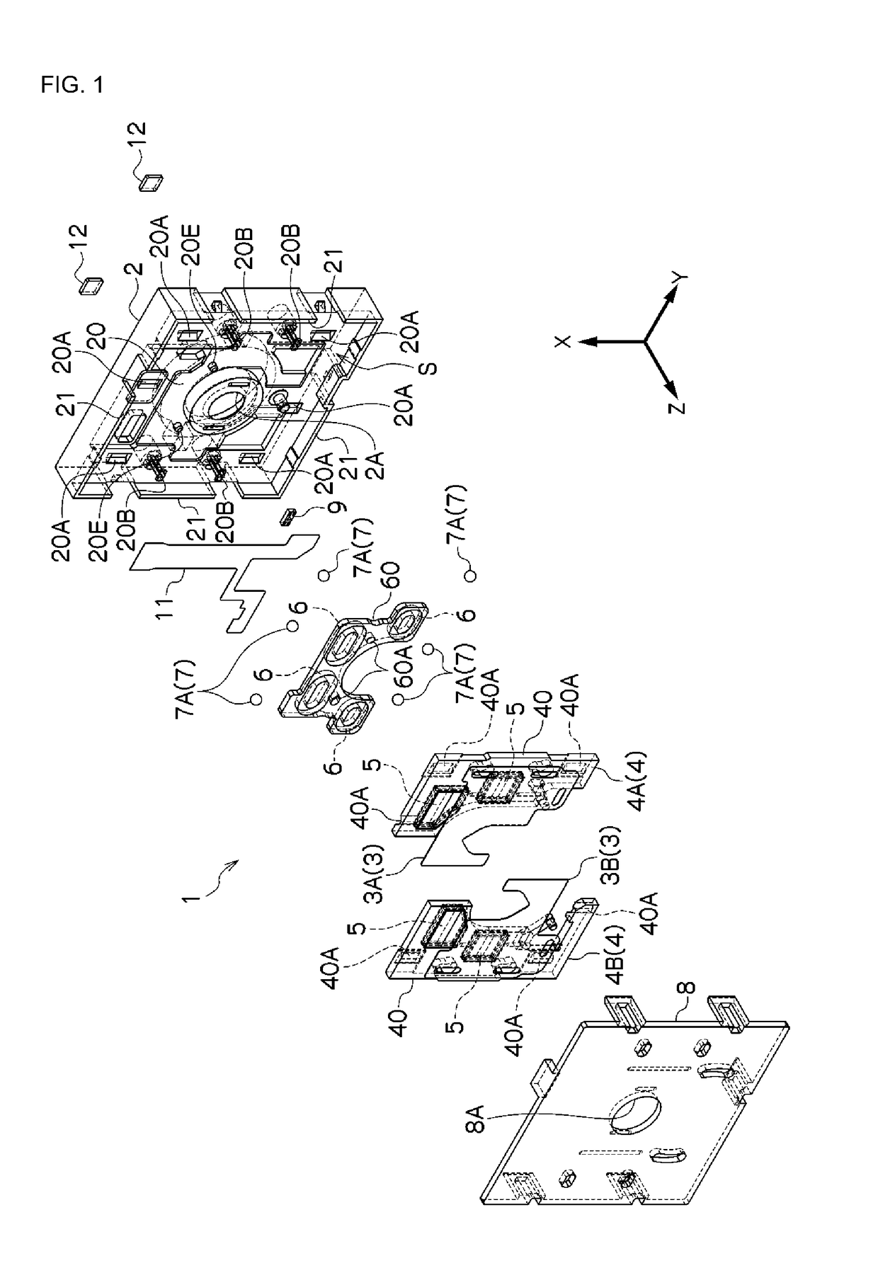
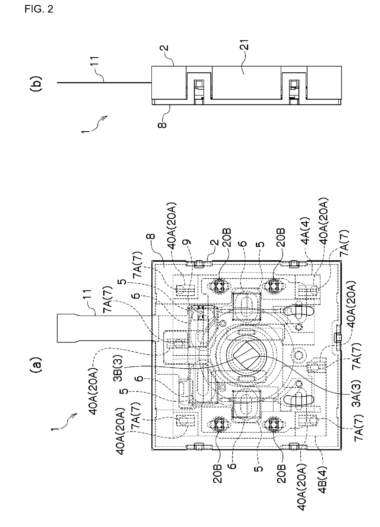
[0083]Examples according to the present invention will be explained below in reference to the drawings. In the explanations below, identical reference symbols are assigned for identical positions in the different drawings, and redundant explanations are omitted. In the various drawings, the optical axial direction is defined as the Z direction, an axial direction within a plane that is perpendicular to the optical axis is defined as the X direction, and the direction that is perpendicular to the X direction within the plane that is perpendicular to the optical axis is defined as the Y direction. FIG. 1 is an exploded perspective diagram illustrating an example of a blade driving device according to an example according to the present invention, and FIG. 2 is a plan view and a side view of a blade driving device according to an example according to the present invention.

[0084]The blade driving device 1 comprises a base member 2, a blade member 3, and a driving member 4. The base memb...


PUM


Abstract

To enable achievement of a reduction in the thickness in a blade driving device that includes a driving member, and to enable a reduction in size of an installation area in a blade driving device that includes a driving member. The blade driving device 1 comprises a base member 2 that has an opening 2A, one or more blade members 3 that operate so as to advance into the opening 2A or withdraw from the opening 2A, and a driving member 4 that is supported on the base member 2 and that moves within a plane that is perpendicular to an optical axis that passes through the opening 2A, for driving the blade member, wherein the driving member 4 is disposed at a position that overlaps the blade member on the periphery of the opening 2A.

Description

CROSS-REFERENCE TO RELATED APPLICATIONS[0001]This is a U.S. national phase application under 35 U.S.C. §371 of International Patent Application No. PCT / JP2016 / 055766, filed Feb. 26, 2016, and claims benefit of priority to Japanese Patent Application No. 2015-039576, filed Feb. 27, 2015; Japanese Patent Application No. 2015-074383, filed Mar. 31, 2015; and Japanese Patent Application No. 2015-074384, filed Mar. 31, 2015; Japanese Patent Application No. 2015-074385, filed Mar. 31, 2015; Japanese Patent Application No. 2015-090750, filed Apr. 27, 2015; and Japanese Patent Application No. 2015-090752, filed Apr. 27, 2015; Japanese Patent Application No. 2015-102182, filed May 19, 2015; Japanese Patent Application No. 2015-128507, filed Jun. 26, 2015; Japanese Patent Application No. 2015-179912, filed Sep. 11, 2015; and Japanese Patent Application No. 2015-183797, filed Sep. 17, 2015. The entire contents of these applications are hereby incorporated by reference.FIELD OF TECHNOLOGY[0002]...

Claims


Application Information

Patent Timeline
Patent Type & Authority Applications(United States)
IPC IPC(8): G03B9/06G03B9/14G03B7/00G03B9/36
CPCG03B9/06G03B9/36G03B9/14G03B7/003G02B13/0055G03B9/02G03B11/00G03B2205/0053
Inventor SHIKAMA, KAZUOBAI, LONGJIWATANABE, NOBUAKI
Owner COPAL CO LTD
Why Eureka
Try Eureka