
Robot for handling object

Inactive Publication Date: 2012-03-22
HONG FU JIN PRECISION IND (SHENZHEN) CO LTD +1
View PDF18 Cites 31 Cited by
  • Summary
  • Abstract
  • Description
  • Claims
  • Application Information

AI Technical Summary

Benefits of technology

[0004]Many robotic arms include a fixed base, a frame pivotably connected to the fixed base about a first rotation axis, a first segment, one end of which is pivotably connected to the frame about a second rotation axis, and a second segment, one end of which is pivotably connected to the other end of the first segment about a third rotation axis. An actuator, such as a detector, a welding device, a gripper or a cutting tool, is mounted at a distal end of the second segment of the industrial robot to execute specific tasks. Generally, several axes are utilized to achieve maximum movement of the actuator.

Problems solved by technology

However, the robotic arm generally has a large axial size due to the presence of the motor and speed reducer, and a load weight of the robotic arm is relatively low.

Method used


Image

  • Robot for handling object
  • Robot for handling object
  • Robot for handling object

Examples


Embodiment Construction

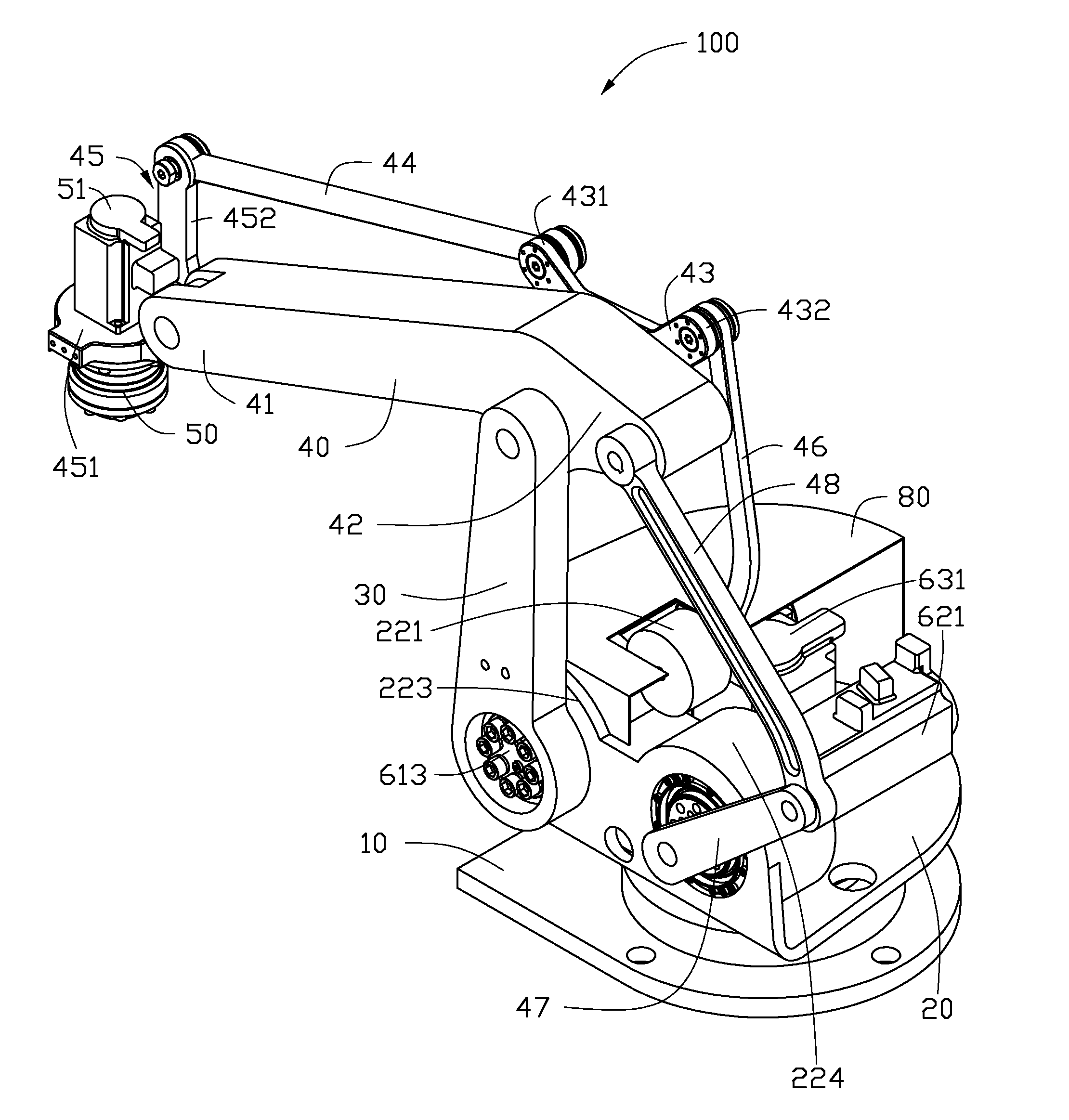
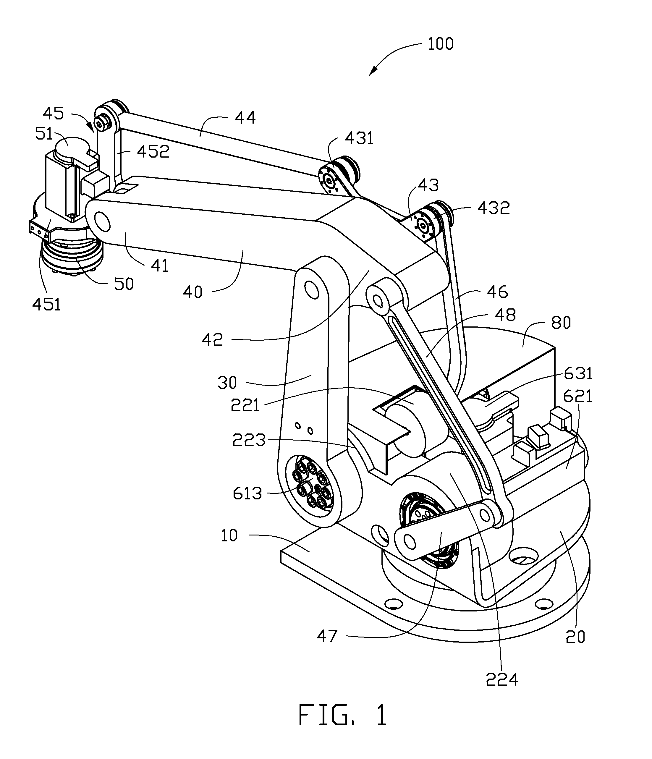
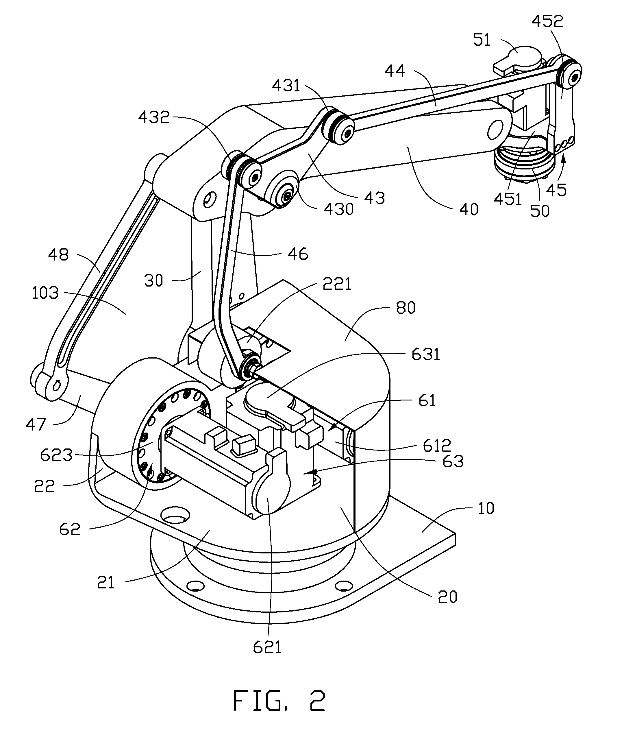
[0011]Referring to FIGS. 1 through 3, an exemplary embodiment of a robot 100 includes a base 10, a support frame 20 rotatably positioned on the base 10, a first robotic arm 30 rotatably connected to the support frame 20, a second robotic arm 40 rotatably connected to the first robotic arm 30, and an actuator 50 positioned on the second robotic arm 40. The second robotic arm 40 forms a first connecting portion 41 and a second connecting portion 42 on opposite ends thereof. The actuator 50 is assembled to the first connecting portion 41, and the first robotic arm 30 is rotatably connected to the second connecting portion 42.

[0012]A connecting member 43 is connected to the second connecting portion 42. A first connecting rod 44 and a second connecting rod 45 are rotatably connected with each other to interconnect the connecting member 43 and the first connecting portion 41. The connecting member 43, the first connecting rod 44, the second connecting rod 45, and the second robotic arm 4...


PUM


Abstract

A robot includes a support frame, a first robotic arm, a second robotic arm, a connecting member, a first connecting rod, a second connecting rod, a third connecting rod, a drive connecting rod, an action connecting rod, and an actuator. The first robotic arm is rotatably connected to the support frame. A second robotic arm is rotatably connected to the first robotic arm. A connecting member is rotatably connected to the second robotic arm. A first connecting rod and a second connecting rod connecting with each other to interconnect the connecting member and the second robotic arm. A third connecting rod is rotatably connected to the support frame and the connecting member. A drive connecting rod is rotatably connected to support frame. An action connecting rod connects the drive connecting rod to the second robotic arm. An actuator is connected to the second connecting rod.

Description

BACKGROUND[0001]1. Technical Field[0002]The present disclosure relates to robots and, particularly, to a robot used for handling objects.[0003]2. Description of Related Art[0004]Many robotic arms include a fixed base, a frame pivotably connected to the fixed base about a first rotation axis, a first segment, one end of which is pivotably connected to the frame about a second rotation axis, and a second segment, one end of which is pivotably connected to the other end of the first segment about a third rotation axis. An actuator, such as a detector, a welding device, a gripper or a cutting tool, is mounted at a distal end of the second segment of the industrial robot to execute specific tasks. Generally, several axes are utilized to achieve maximum movement of the actuator.[0005]In robots of this kind, each arm rotates around a rotation axis driven by a driving unit. Typically, the driving unit includes a motor mounted on the first segment and a speed reducer coupled to the motor to ...

Claims


Application Information

Patent Timeline
IPC IPC(8): B25J18/00B25J17/00
CPCY10T74/20305B25J9/106
Inventor CHEN, WEN-SHENGLI, HAI-YUAN
Owner HONG FU JIN PRECISION IND (SHENZHEN) CO LTD
Learn More