Retainer with band clip and cable holder

Inactive Publication Date: 2007-11-13
YAZAKI NORTH AMERICA
View PDF8 Cites 29 Cited by
  • Summary
  • Abstract
  • Description
  • Claims
  • Application Information

AI Technical Summary

Benefits of technology

[0008]Another object of the invention is to form the holder integral with the band clip to provide a one-piece, compact retainer.
[0009]A further object of the invention is to arrange

Problems solved by technology

Placing additional apertures in the vehicle panels for separate clips raises manufacturing costs and can weaken the structural integrity of the panel.
In addition, using a larger number of clips increases assembly and material costs.
Furthermore,

Method used


Image

  • Retainer with band clip and cable holder
  • Retainer with band clip and cable holder
  • Retainer with band clip and cable holder

Examples


Example

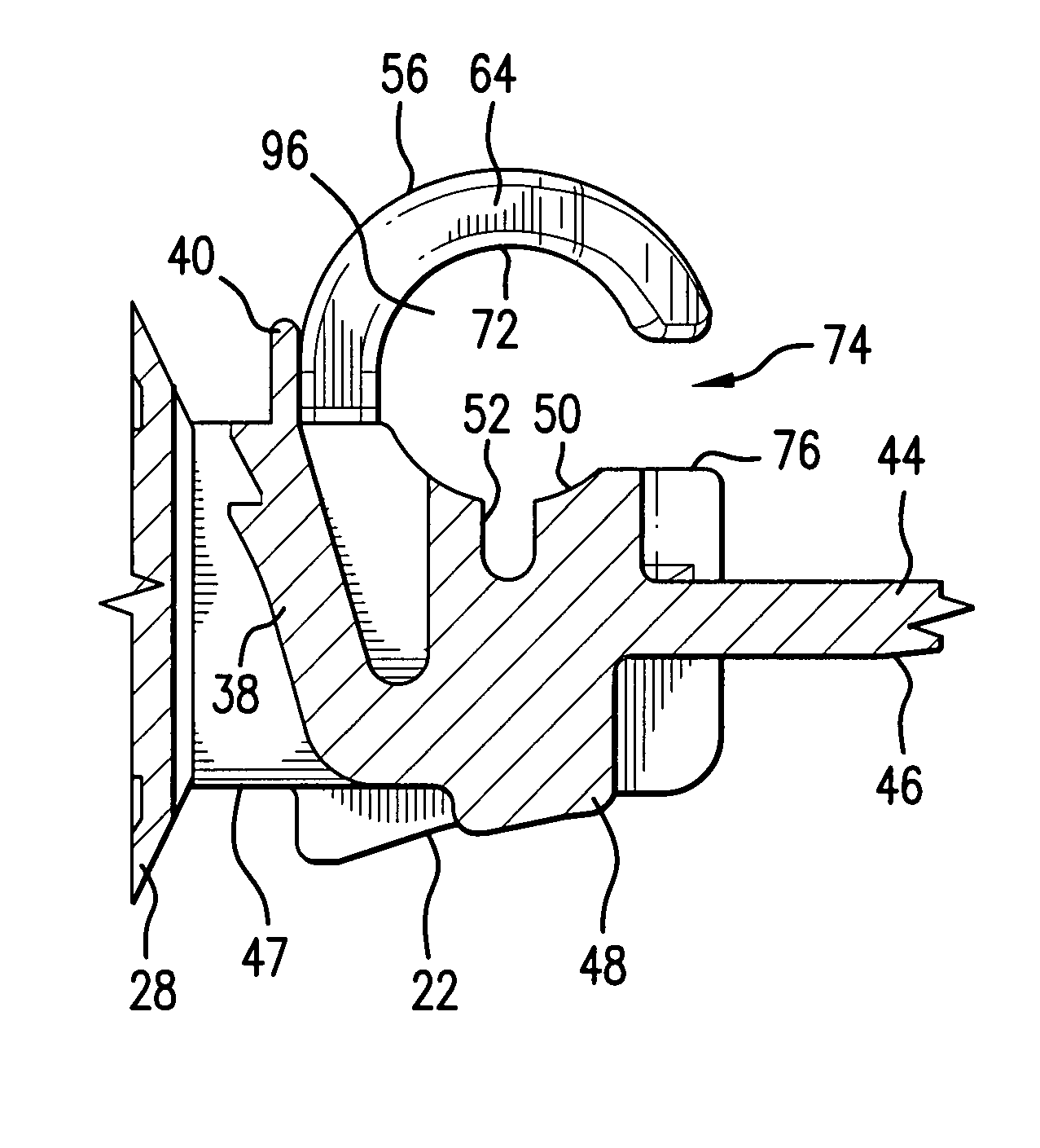
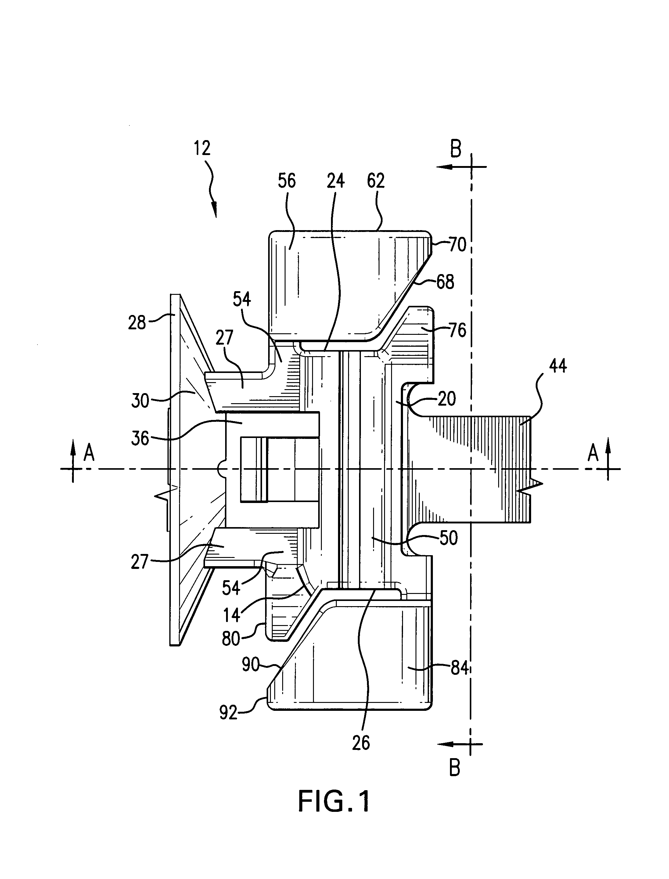
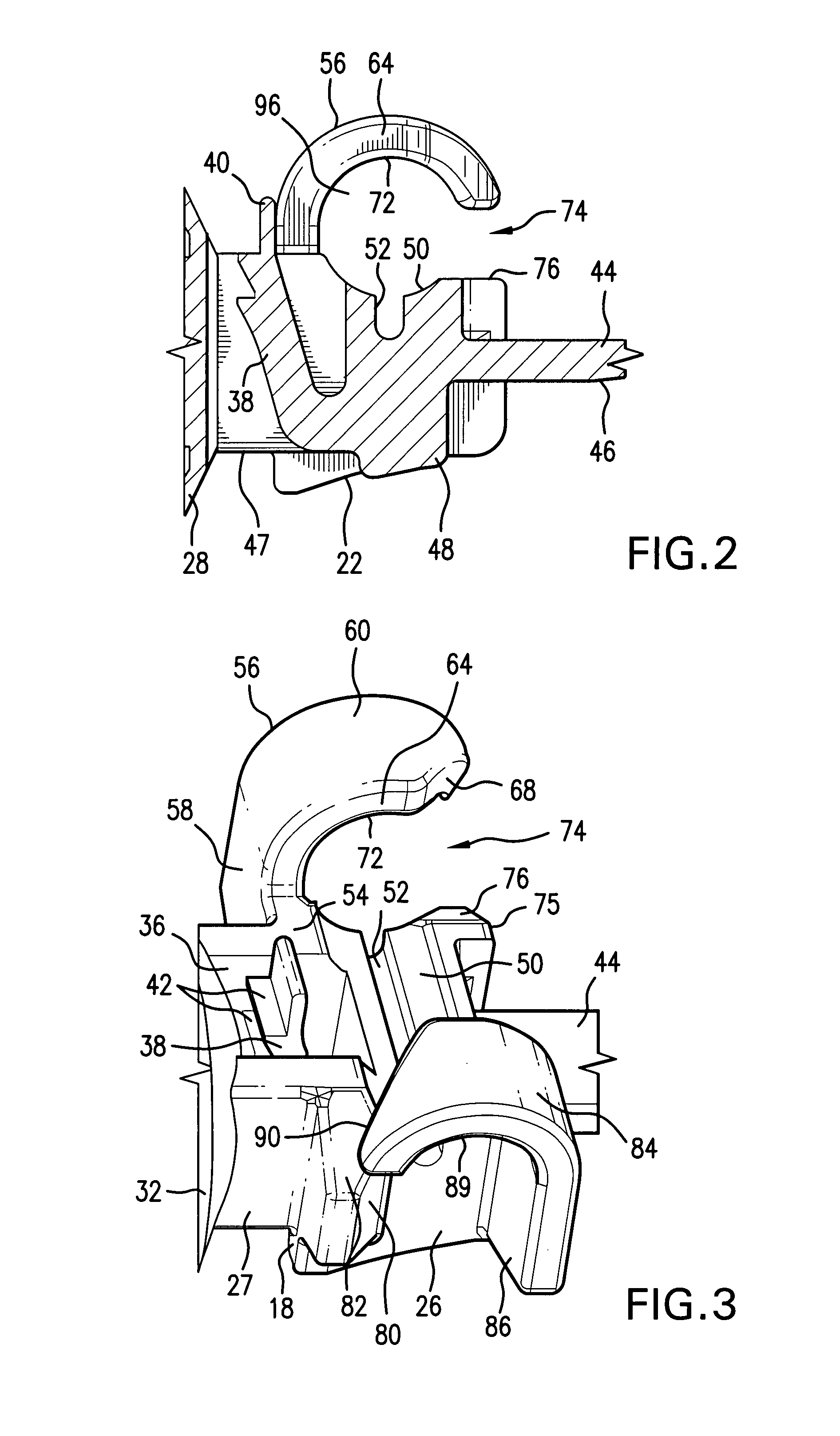
[0022]Referring now to FIGS. 1-5, a unitary retainer 12 including a band clip and a cable or hose holder according to the present invention is illustrated. The retainer would be, for example, injection molded in one piece from an electrically nonconductive, somewhat resilient material such as polypropylene or Nylon.

[0023]The retainer 12 has a base 14 with a front surface 16, a rear surface 18, an upper side 20, an underside 22, and two opposite ends or end walls 24 and 26. Supports 27 protrude from the rear surface 18 of the base to join with a circular stabilizing plate 28. The stabilizing plate 28 has the configuration of a shallow bowl. The supports 27 are joined to a convex side 30 of the plate. The plate 28 has a concave side 32, broadly represented in FIG. 3, from which a push-in clip or fastener 34, partially shown in FIG. 5, extends. The fastener 34 is conventional and may be, for example, an arrowhead-type clip or a Christmas-tree-type clip. The fastener 34 is designed to b...


PUM


Abstract

A one-piece retainer has a base with an integral band clip and a fastener for securing an electrical cable or wire harness to a vehicle component, as well as a pair of arms for supporting another cable or a hose on the component. The base has a cradle extending along a length of the base. The arms extend from each end of the base outward from the cradle. The arms have curved sections creating interior spaces aligned with and spaced away from the cradle. Ledges extend from the base opposite each arm, forming an opening to each interior space between the ledge and a tapered edge of the curved section of the arm. The openings face in opposite directions. A cable or hose is twisted or turned relative to the base such that part of the cable or hose can be rested on the ledges in alignment with each opening. Then the cable or hose is twisted or turned back and inserted or snapped into the interior of each arm to seat along the cradle. The arms resiliently clasp the cable or hose in the cradle.

Description

BACKGROUND OF THE INVENTION[0001]1. Field of the Invention[0002]The invention relates in general to clips for securing electrical cables to vehicle panels, and more particularly to a retainer that includes a band clip and a separate holder for an additional cable or hose.[0003]2. Discussion of Related Art[0004]Cable ties or band clips are typically used in vehicle wiring systems to secure wire bundles or harnesses at specific locations in the vehicles along the routes of the harnesses. A fastener attached to the tie or clip is often pushed into an aperture in a vehicle bulkhead or panel after the tie or band is wrapped around the harness. An example of this type of clip is described in U.S. Pat. No. 5,131,613.[0005]Sometimes it is necessary to secure other cables or hoses along the length of, or part of the length of, the same route in a compact arrangement. Many of these cables or hoses should not be used with ties or bands that might crimp or otherwise damage the cable or hose, so...

Claims


Application Information

Patent Timeline
IPC IPC(8): H02G3/04
CPCB60R16/0215F16L3/1215H02G3/30F16L3/237F16L3/137
Inventor WATTHANASINTHAM, MALAYTHIP
Owner YAZAKI NORTH AMERICA
Why Eureka
Try Eureka