Clamp assembly for a steering column assembly

a technology for steering column and clamp assembly, which is applied in the direction of snap fasteners, buckles, transportation and packaging, etc., can solve the problems of teeth or locking mechanism damag

Inactive Publication Date: 2013-04-09
TRW LIMITED
View PDF13 Cites 32 Cited by
  • Summary
  • Abstract
  • Description
  • Claims
  • Application Information

AI Technical Summary

Benefits of technology

[0019]This assembly is advantageous because both inner and outer blocks are sprung, and some lost motion is provided between the inner / outer blocks and the retaining clip of the clamp block. The assembly can therefore help prevent tooth damage in a tooth on tooth event by allowing the potentially damaging forces to be absorbed by the springs whilst ensuring that the racks of teeth engage as soon as the racks move out of the tooth on tooth position due to the biasing of the second and third springs. Because the inner and outer blocks are independently retained by the retaining clip, second / third springs and clamp block it is possible for one rack of teeth to absorb a tooth on tooth event whilst the other racks(s) of teeth can still fully engage.
[0023]The hooked arms may be located within grooves provided in inner block and outer block. This protects the arms from damage.
[0029]The inner block may be nested within the outer toothed block so that the outer toothed block is supported and guided through its movement by a sliding engagement with the inner block, the inner block having a sliding engagement with the clamp pin. The outer block may therefore be hollow. There may be a sliding engagement between the outwardly facing surface of the inner block and the inwardly facing surface of the outer block. The inner block may therefore prevent any significant movement of the outer block other than in a direction parallel to the axis of the clamp pin, i.e. towards and away from the fixed rack portion. It may be possible, nevertheless for both the inner and outer blocks to be guided by the clamp pin, with the inner block not guiding the outer block, or only providing some additional guiding of the outer block.

Problems solved by technology

However, a basic problem with the use of teeth in this way is that on occasions the tips of the teeth on one part may be exactly in line with the tips of the teeth that should engage them when the driver attempts to move the clamp to the locked position.
This so called tooth-on-tooth problem can either prevent the driver locking the clamp properly or in extreme cases damage the teeth or the locking mechanism.

Method used


Image

  • Clamp assembly for a steering column assembly
  • Clamp assembly for a steering column assembly
  • Clamp assembly for a steering column assembly

Examples


Embodiment Construction

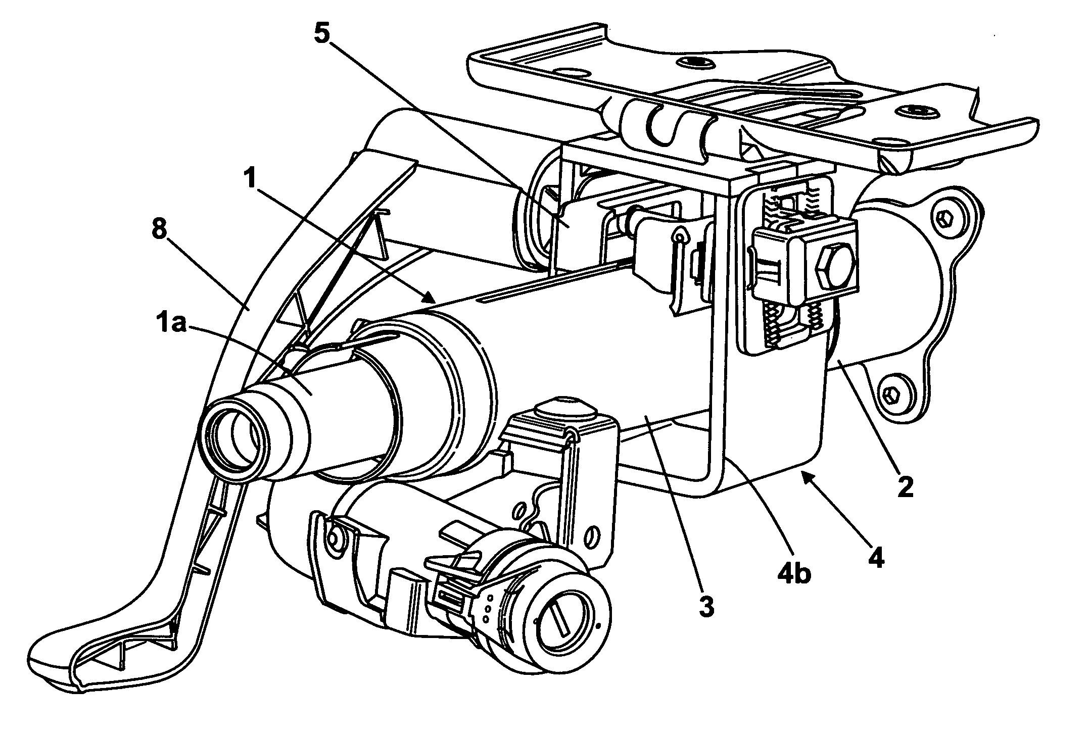
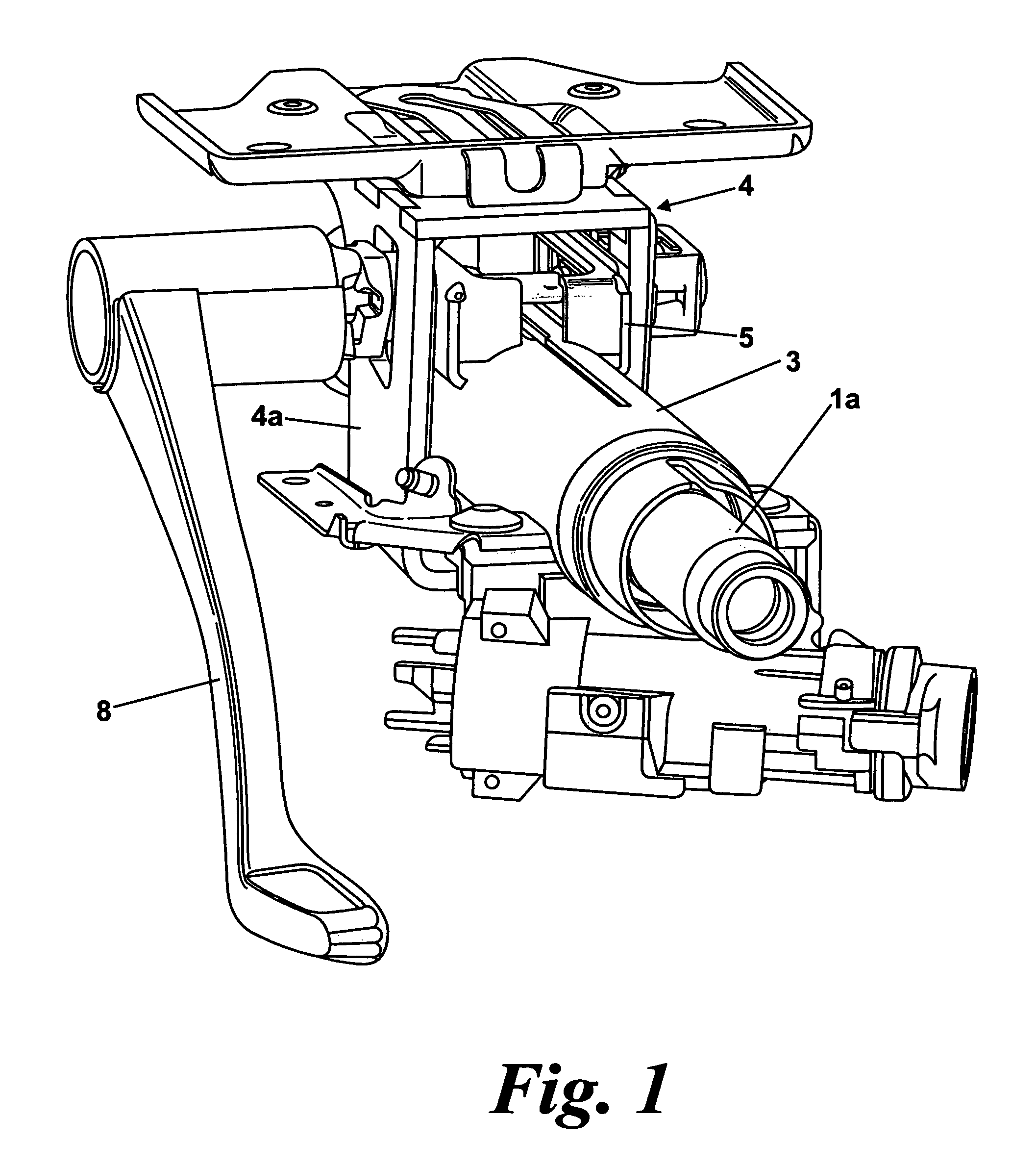
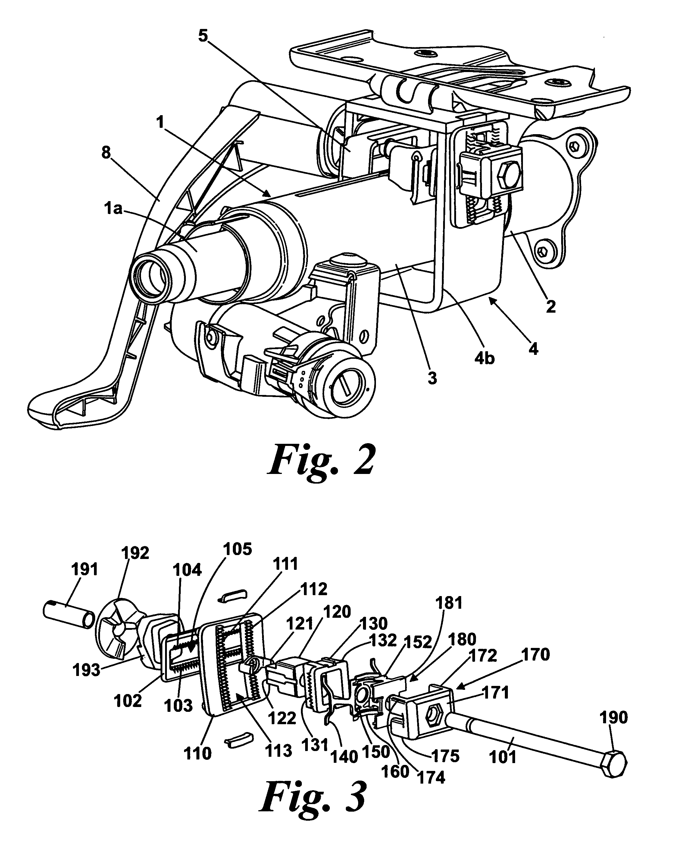
[0049]An embodiment of a steering column assembly for a vehicle which incorporates a clamp assembly according to a first aspect of the invention is shown in FIGS. 1 and 2 of the accompanying drawings. It comprises a telescopic steering column shroud having an upper portion 3 and a lower portion 2 that fits around a telescopic steering shaft (1a as shown in FIGS. 1 and 2). The upper portion 3, referred to herein as a moving portion, can slide up and down the lower portion to enable the length of the shroud to be adjusted.

[0050]The movement of the moving portion 3 is achieved by supporting it within two downwardly extending arms 4a, 4b of a support bracket 4. The bracket 4 will be referred to herein after as the fixed portion, being considered fixed in that it is fixed relative to the vehicle body (not shown). The moving portion 3 is reinforced by a box section rail 5 welded to it to prevent it collapsing and this box section 2 fits snugly between the two arms 4a,4b of the bracket 4.

[...


PUM


Abstract

A clamp assembly secures a fixed portion of a steering column assembly to a movable portion of a steering column. It comprises a rack of teeth carried by the moving portion and a rack of teeth carried by the fixed portion and an inner hollow toothed block nested inside an outer hollow toothed block, each carrying at least one rack of teeth with the rack of teeth on the inner block facing the rack of teeth on the moving portion and the rack of teeth on the outer block facing the rack of teeth on the fixed portion. A retaining clip provides a lost motion coupling between the retaining clip and the inner toothed block and an independent lost motion coupling between the retaining clip and the inner toothed block and an independent motion coupling between the retaining clip and the outer toothed block. First, second and third springs bias the teeth of the blocks into and out of engagement with the racks when locked and unlocked. The assembly helps prevent damage to the teeth with the springs permitting the damage force on the blocks to be independently absorbed.

Description

CROSS-REFERENCE TO RELATED APPLICATIONS[0001]This application is a national stage of International Application No. PCT / GB2008 / 003431 filed Oct. 10, 2008, the disclosures of which are incorporated herein by reference in entirety, and which claimed priority to Great Britain Patent Application No. 0719971.4 filed Oct. 12, 2007, the disclosures of which are incorporated herein by reference in entirety.BACKGROUND OF THE INVENTION[0002]This invention relates to improvements in clamp assemblies for steering column assemblies, especially but not exclusively to electric power assisted steering assemblies. In particular it relates to clamp assemblies for steering column assemblies adjusted for both rake and reach.[0003]It is known to provide a steering column assembly in which a steering wheel is connected to one or more road wheels through a collapsible or telescopic steering column shaft. The shaft is designed to collapse away from a driver of the vehicle if a load is applied to the steerin...

Claims


Application Information

Patent Timeline
Patent Type & Authority Patents(United States)
IPC IPC(8): B62D1/18B62D1/00
CPCB62D1/184Y10T24/44017
Inventor DAVIES, NICLASHAVLICEK, JAN
Owner TRW LIMITED
Why Eureka
Try Eureka