Non-impact keyless chuck

a keyless, non-impact technology, applied in the direction of chucks, mechanical equipment, manufacturing tools, etc., can solve the problems of limited tightening or loosening torque which may be applied directly in the hand operation, personal injury, and time-consuming two-handed operation, so as to increase the effective diameter of the body, reduce friction losses in the mechanism, and increase the effective tightening torque

Inactive Publication Date: 2006-05-16
JACOBS CHUCK MFG CO THE
View PDF50 Cites 5 Cited by
  • Summary
  • Abstract
  • Description
  • Claims
  • Application Information

AI Technical Summary

Benefits of technology

[0009]In accordance with the present invention, a keyless chuck of the non-impact type is provided. The invention employs an anti-friction bearing interposed between the nut and the body to decrease the friction losses in the mechanism so as to increase the effective tightening torque. The bearing thrust ring is formed separately from the body member and pressed thereon so as to increase the effective diameter of the body while minimizing the machining requirements. The principal load-bearing parts of the chuck, i.e., the jaws, body, nut, bearing and bearing race are formed from metal while the front and back sleeves and related parts may be formed from plastic materials so as to reduce the cost and permit customizing of the chuck.

Problems solved by technology

However, because the tightening or loosening torque which may be applied directly in a hand operation is limited, the art developed the so-called three-jaw geared chuck.
However, the separate key may easily be misplaced or accidentally left in the chuck when the driver is actuated, thus possibly leading to some personal injury.
In addition, the chucking or unchucking operation is a two-handed procedure which is time consuming.

Method used


Image

  • Non-impact keyless chuck
  • Non-impact keyless chuck
  • Non-impact keyless chuck

Examples


Embodiment Construction

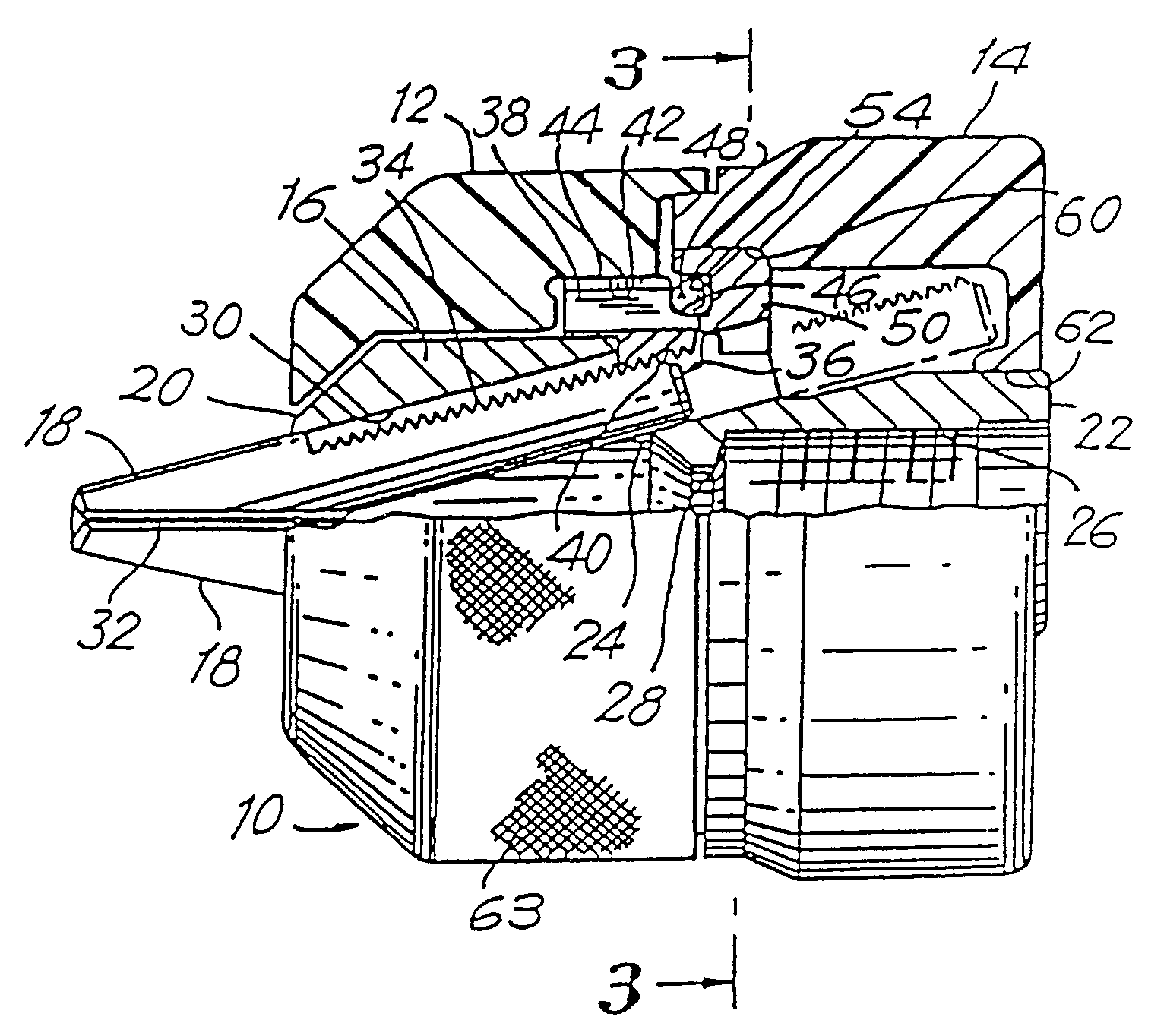
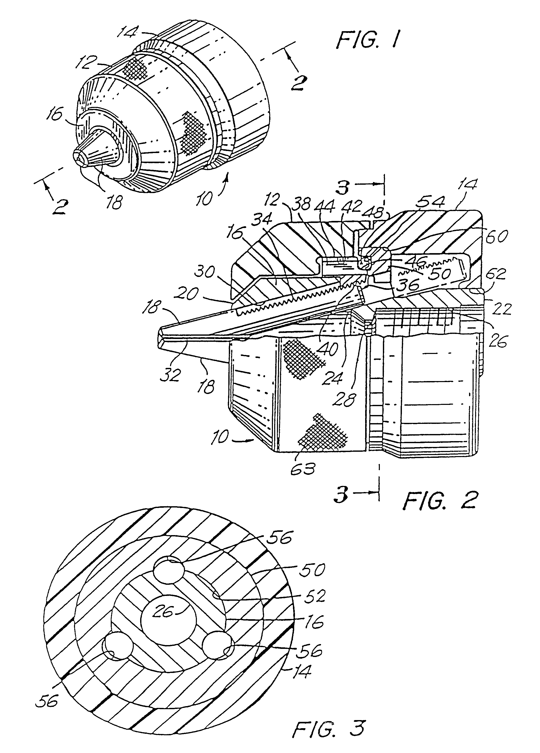
[0031]Referring now to FIG. 1, there is illustrated a chuck 10 in accordance with the present invention. The chuck 10 includes a front sleeve member 12, an optional rear sleeve member 14, a body member 16 and jaws 18.

[0032]As shown more clearly in FIG. 2, the body member 16 is generally cylindrical in shape and comprises a nose or forward section 20 and a tail or rearward section 22. The nose section 20 is, preferably, chamfered at its outer end. An axial bore 24 is formed in the nose section 20 of the body member 16. Axial bore 24 is somewhat larger than the largest tool shank which the chuck is designed to accommodate. A threaded bore 26 is formed in the tail section 22 of the body 16 and is of a standard size to mate with the threaded drive shaft of a powered or hand driver (not shown). The bores 24, 26 may communicate at the central region 28 of the body member 16. If desired, the threaded bore 26 may be replaced by a tapered, unthreaded bore of a standard size to mate with a ta...


PUM


Abstract

A non-impact keyless chuck suitable for use with manual or powered drivers is disclosed. The chuck comprises a body which carries a rotatable split nut having a relatively fine thread and a plurality of slidable jaws, which may be identical, driven by the rotatable nut. An anti-friction bearing is disposed between the rotatable nut and a bearing thrust ring mounted on the body. A clutch or torque limiting mechanism is provided to limit the tightening torque to a predetermined value while the loosening torque may be limited or unlimited. The front sleeve, and rear sleeve, if used, may be formed from a structural plastic to reduce manufacturing costs. A relatively soft elastomeric grip boot may be placed on the front sleeve to improve the grip and temporarily restrain and center the tool during chuck tightening or loosening operations. A relatively soft elastomeric grip boot may also be placed on the rear sleeve, if used.

Description

CLAIM OF PRIORITY[0001]The present application is a continuation of application Ser. No. 09 / 954,829, filed Sep. 12, 2001 now U.S. Pat. No.6,699,207, which is a continuation of application Ser. No. 09 / 570,427, filed May 12, 2000, now U.S. Pat. No. 6,296,257, which is a continuation of application Ser. No. 09 / 329,700, filed Jun. 10, 1999, now U.S. Pat. No. 6,286,842, which is a continuation of application Ser. No. 08 / 704,418, filed Aug. 20, 1996, now U.S. Pat. No. 5,924,702, which is a continuation of application Ser. No. 08 / 476,896, filed Jun. 7, 1995, now U.S. Pat. No. 5,573,254, which is a continuation of application Ser. No. 08 / 322,356, filed Oct. 13, 1994, now U.S. Pat. No. 5,452,906, which is a continuation of application 08 / 234,227, filed Apr. 28, 1994, now abandoned, which is a continuation of application 08 / 099,160, filed Jul. 29, 1993, now U.S. Pat. No. 5,330,204, which is a continuation of application Ser. No. 07 / 884,205, filed May 18, 1992, now U.S. Pat. No. 5,253,879, whi...

Claims


Application Information

Patent Timeline
Patent Type & Authority Patents(United States)
IPC IPC(8): B23B31/10B23B31/12
CPCB23B31/123B23B31/1238B23B2226/33B23B2228/10Y10T279/17615B23B2231/38B23B2231/44Y10S279/902Y10T279/17632B23B2231/14
Inventor HUFF, ROBERT O.JORDAN, PAUL T.FORGUER, WILLIAM F.
Owner JACOBS CHUCK MFG CO THE
Why Eureka
Try Eureka