Variable displacement pump with a suction area groove for pushing out rotor vanes

a variable displacement pump and suction area technology, applied in the direction of machines/engines, positive displacement liquid engines, liquid fuel engines, etc., can solve the problems of inability to apply pressure on the base end portion of the vane, variable displacement pumps cannot start discharging, etc., to achieve the effect of effectively utilizing the pump discharge flow, reducing drive power, and low slide resistan

Inactive Publication Date: 2006-07-04
HITACHI ASTEMO LTD
View PDF23 Cites 35 Cited by
  • Summary
  • Abstract
  • Description
  • Claims
  • Application Information

AI Technical Summary

Benefits of technology

[0010]The present invention has been achieved to solve the above problems, and it is an object of the invention to provide a variable displacement pump capable of effectively utilizing a pump discharge flow without detracting a pressing force of the vane against the cam ring, and capable of reducing a drive power with a low slide resistance.
[0014]In the constitution of this variable displacement pump, because a higher pressure than the suction pressure acting on the top end portion of the vane is applied to the base end portion of the vane, the vane can be surely pressed against the cam ring without shortage of a pressing force for pressing the vane against the cam ring. Unlike the case where the pump discharge pressure is introduced, the pump discharge flow can be fully utilized for the fluid pressure utilization apparatus to reduce the drive power. Furthermore, the drive power for the pump can be reduced with lower friction loss between the vane and the cam ring because the vane is not pressed against the cam ring with excessive force.
[0016]In the variable displacement pump of this constitution, if the vane slightly jutted out due to a centrifugal force at the start time is contacted with the inner face of the cam ring near the end portion in the discharge area and pushed into the inside of the slit, the oil on the bottom portion of the slit is pushed out and introduced into the bottom portion of the subsequent vane that is not yet contacted with the cam ring, so that the vane is pushed out and pressed against the inner circumferential face of the cam ring, whereby the discharge of oil can be started rapidly at the start time.
[0018]In the variable displacement pump of this constitution, at the start time, the discharge of oil can be started rapidly by pressing the vane against the cam ring as rapidly as possible, and the vane can be pressed against the cam ring with an adequate force by introducing an optimal pressure into the base end side of the vane, while driving.

Problems solved by technology

However, at the start time when the discharge of oil is not started, a pressure to be applied on the base end portion of vane can not be obtained.
At this point of time, the vane is simply jutted out due to a centrifugal force of the rotating rotor, in which the top end of vane is out of contact with the inner face of the cam ring, because the vane is insufficiently jutted out, resulting in a problem that the variable displacement pump can not start discharging in any way.

Method used


Image

  • Variable displacement pump with a suction area groove for pushing out rotor vanes
  • Variable displacement pump with a suction area groove for pushing out rotor vanes
  • Variable displacement pump with a suction area groove for pushing out rotor vanes

Examples


first embodiment

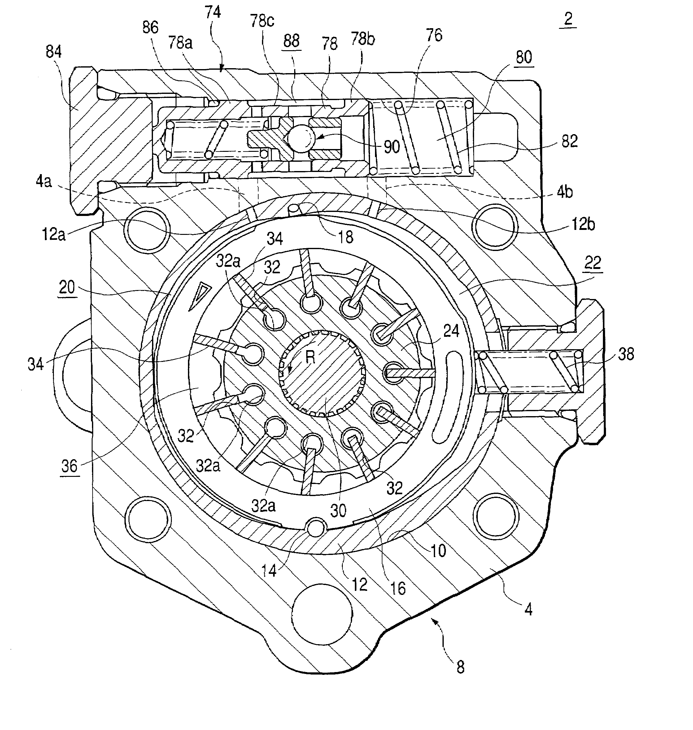
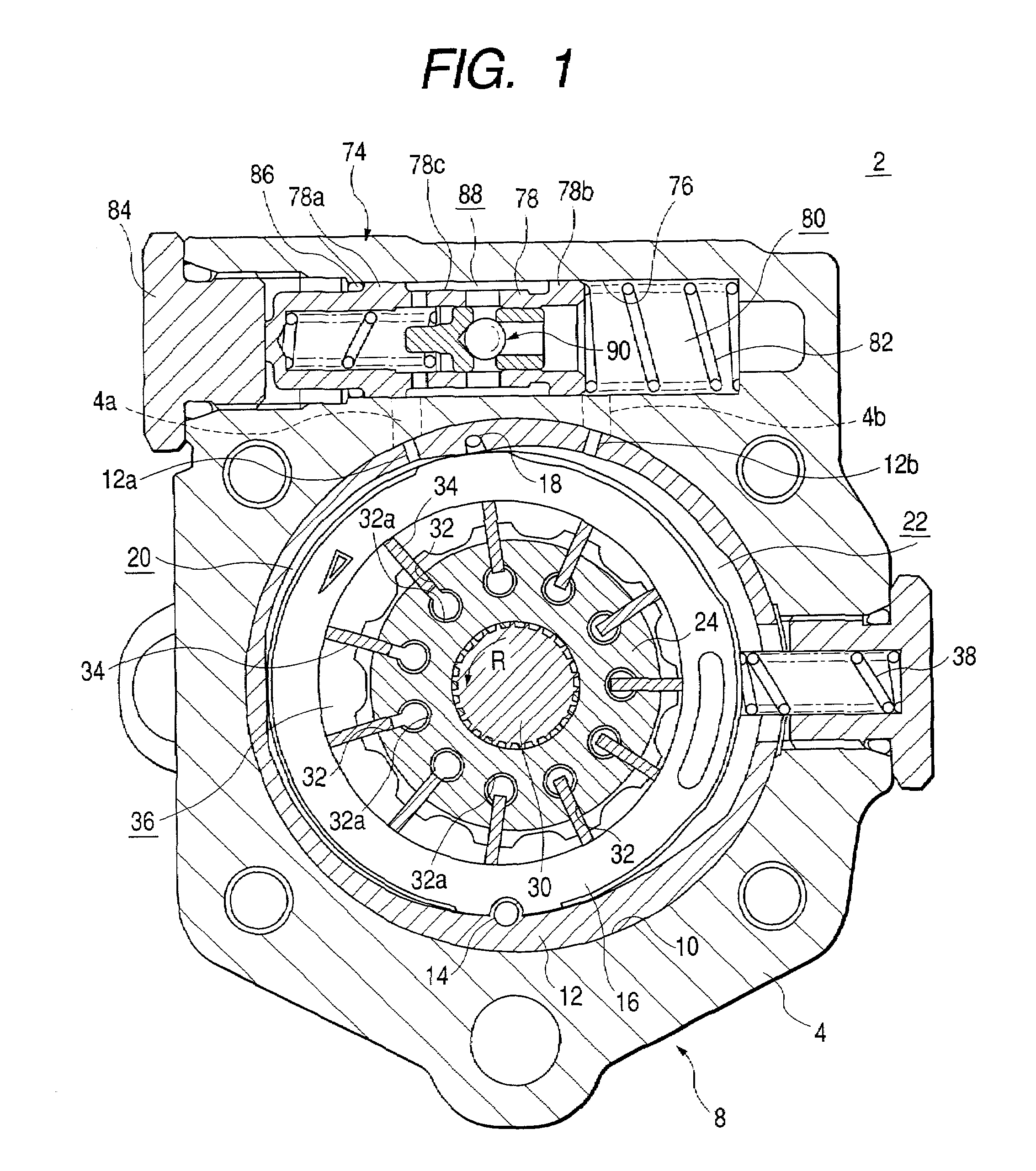
[0074]In the first embodiment, the circular grooves 60 and 66 in the suction area A formed in the pressure plate 40 and the rear body 6 disposed on both sides of the rotor 24 and the cam ring 16 have the same shape. The circular grooves 70 and 72 in the discharge area B also have the same shape. However, in this embodiment, of the circular grooves for introducing oil pressure into the back pressure inlet bore 32a, the circular grooves 460 and 466 formed in the suction area A have the same shape in the pressure plate 40 and the rear body (other plate) 6, while the circular grooves 470 and 472 formed in the discharge area B have different shapes in the pressure plate 40 and the rear body 6.

[0075]The circular grooves 466 and 460 formed in the suction area A of the pressure plate 40 and the rear body 6 has a length contained within the suction area A. On the other hand, the circular groove 472 formed in the discharge area B of the rear body 6 has its start point 472a located close to th...

fifth embodiment

[0082]A variable displacement pump according to the invention has the circular grooves 470 and 472 shaped as shown in FIGS. 13 and 14. The communicating passage 471 between the circular groove 470 in the discharge area B of the pressure plate 40 and the discharge pressure chamber 50 is formed into the restricted passage. Therefore, the start number of rotations for the variable displacement pump can be greatly reduced. Furthermore, in addition to this constitution, the relief passage 68 for introducing the oil relieved from the relief valve 90 and the inlet passage 108 for introducing the oil leaked from the circular grooves 470 and 472 in the discharge area B via an clearance on the side face of the rotor 24 around the outer circumference of the drive shaft 30 are provided. Therefore, the vane 34 can be pressed against the inner circumferential cam face of the cam ring 16 with an adequate force, while the variable displacement pump is operating, as with other embodiments.

[0083]Inst...


PUM


Abstract

A variable displacement pump has a cam ring, a rotor, a plurality of vanes, a pressure plate and a rear body. The cam ring is accommodated within a pump body. The rotor rotates within the cam ring. The plurality of vanes are inserted retractably into slits formed at regular intervals circumferentially in the rotor. The pressure plate and the rear body carry the cam ring and the rotor. A circular groove communicating to a back pressure inlet bore on a bottom portion of the slits is formed in a suction area on a face of the rear body on a side of the rotor. The groove is communicated via a communication passage to a passage between a power steering gear and a tank T to introduce a working oil after used in the power steering gear.

Description

[0001]The present disclosure relates to the subject matter contained in Japanese Patent Application No.2001-297103 filed on Sep. 27, 2001 and Japanese Patent Application No.2002-067248 filed on Mar. 12, 2002, which are incorporated herein by reference in its entirety.BACKGROUND OF THE INVENTION[0002]1. Field of the Invention[0003]The present invention relates to a variable displacement pump useful as a pressure supply source of a pressure fluid utilization apparatus such as a power steering gear for the vehicle.[0004]2. Description of the Related Art[0005]A variable displacement pump of vane type typically includes a cam ring having a cam face on the inner circumference thereof, a rotor rotating within the cam ring, a plurality of vanes inserted retractably into slits formed at regular intervals circumferentially on the outer circumference of the rotor, and two plates (or plate-like pump bodies) carrying the cam ring and the rotor from both sides. Each vane slides with the cam ring ...

Claims


Application Information

Patent Timeline
Patent Type & Authority Patents(United States)
IPC IPC(8): F04B17/03B62D5/07F01C21/08F04C2/344F04C14/00F04C14/06F04C14/10F04C14/22F04C14/24F04C14/26F04C15/06
CPCF01C21/0863F04C14/226F04C2/3442F04C14/00F04C14/10
Inventor KONISHI, HIDEOUCHINO, KAZUYOSHIOKAMOTO, HARUO
Owner HITACHI ASTEMO LTD
Why Eureka
Try Eureka