Transmission fluid heating using engine exhaust

a technology of transmission fluid and engine exhaust, which is applied in the direction of machines/engines, lighting and heating apparatus, machine operation mode, etc., can solve the problems of potential problems and noticeable delay for vehicle occupants, and achieve the effects of reducing frictional losses, fuel economy benefits, and improving fuel economy

Inactive Publication Date: 2005-09-15
FORD GLOBAL TECH LLC
View PDF13 Cites 37 Cited by
  • Summary
  • Abstract
  • Description
  • Claims
  • Application Information

AI Technical Summary

Benefits of technology

[0007] The system allows for the rapid warm up of transmission fluid from a cold start, thereby reducing frictional losses and improving fuel economy. The system increases the temperature of transmission oil during several minutes of operation to achieve a fuel economy benefit. Thereafter, the system prevents the transmission oil from overheating.
[0008] The arrangement offers significant benefits relative to systems that use engine coolant as a source of heat. It can deliver fuel economy benefit without affecting other vehicle attributes. It is simple to implement and calibrate. It offers a protection mechanism against overheating of the transmission oil. It provides a means for heating transmission oil at different temperatures based on ambient temperatures.

Problems solved by technology

While this method is effective, it has potential problems.
By transferring heat from the engine coolant to oil, less heat is available to warm the passenger compartment, which causes a noticeable delay to vehicle occupants especially during cold weather.

Method used


Image

  • Transmission fluid heating using engine exhaust
  • Transmission fluid heating using engine exhaust
  • Transmission fluid heating using engine exhaust

Examples


Embodiment Construction

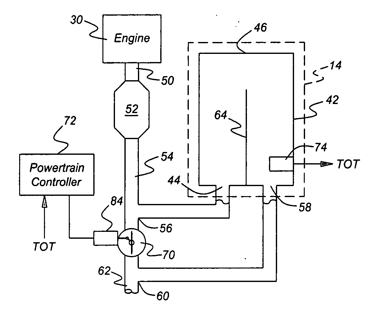
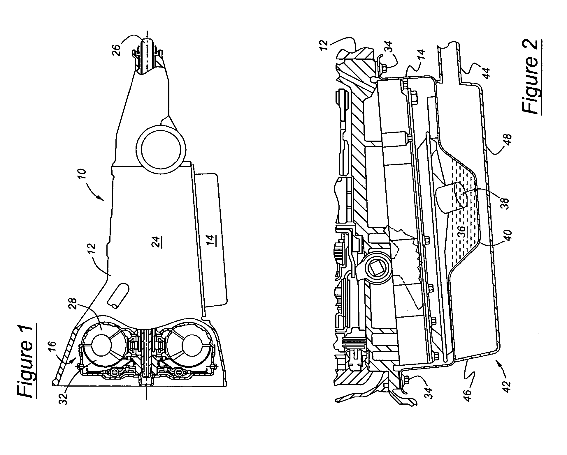
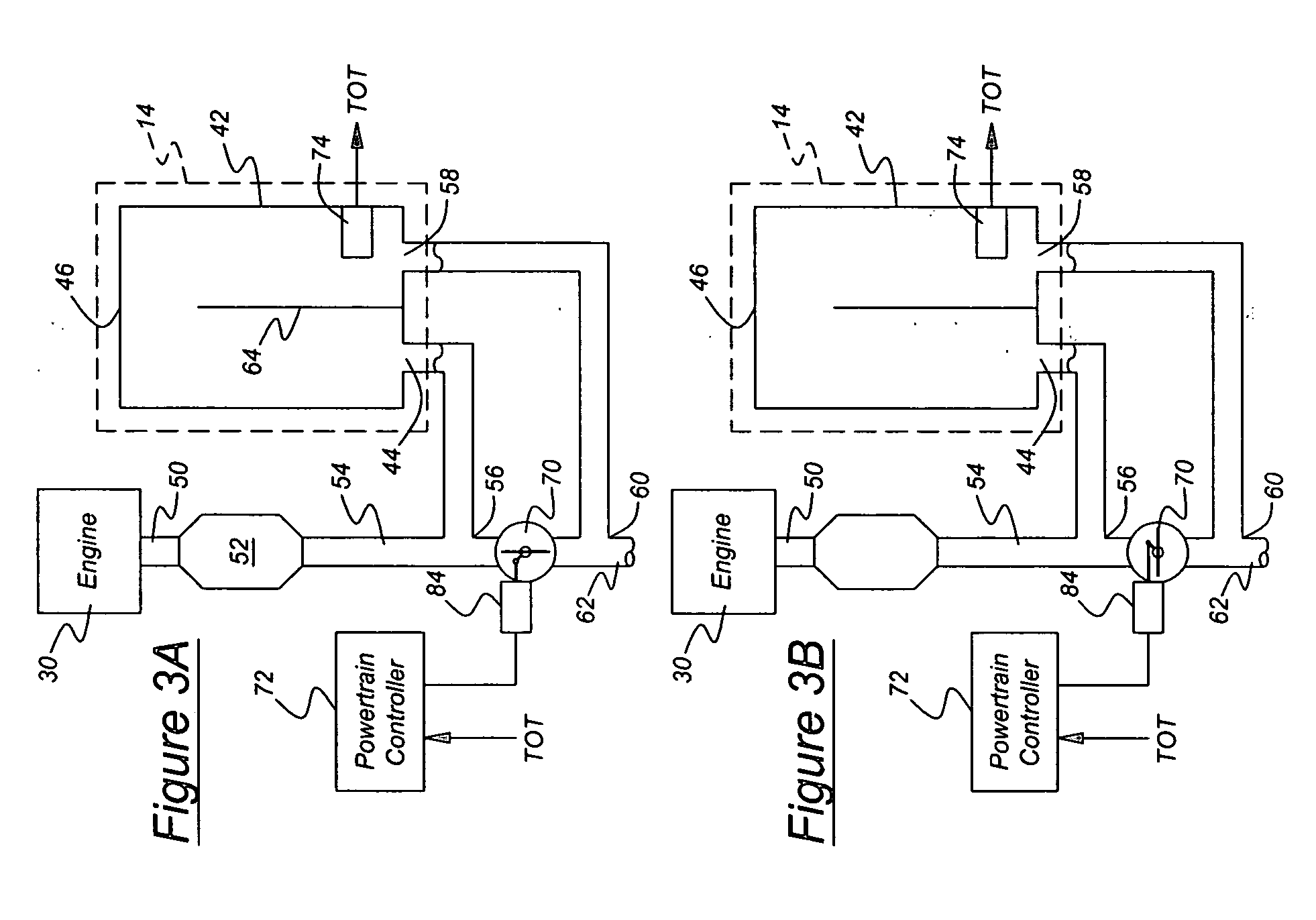
[0017] Referring now to the drawings, there is illustrated in FIG. 1 an automatic transmission 10 packaged in a case 12, and a transmission fluid reservoir or oil pan 14 located below and secured to the case. Located within the case 12, are the transmission components and subsystems including a hydrokinetic torque converter 16, gearing 24 and an output shaft 26. Transmission fluid, sometimes called “oil,” circulates within the transmission in a hydraulic system under pressure produced by a hydraulic pump; flows from the case to an external oil cooler, which extracts heat from the fluid; and returns to the oil pan 14 from the cooler. Heat from the transmission fluid is exchanged in the cooler principally by convection to air passing at high speed between fins radiating from the lines that carry the fluid through the cooler and by conduction to surrounding fluid.

[0018] The torque converter 16 includes a bladed impeller wheel 28 driven by an engine 30 (see FIGS. 3A and 3B). A bladed t...


PUM


Abstract

A heat exchanger integrated into the transmission oil pan transfers heat from post-catalyst exhaust gases to the transmission oil. Inlet and outlet ducts route exhaust gas between the heat exchanger and an exhaust pipe located downstream of the catalyst. The exhaust pipe accommodates a control valve that diverts exhaust gas flow to the heat exchanger during the warm-up phase, or to the tailpipe during steady state operation. A control function is provided to monitor transmission oil temperature and engine operating conditions and to control actuation of the valve. The main input parameter to the control function is the transmission oil temperature.

Description

BACKGROUND OF THE INVENTION [0001] The invention relates to heating transmission oil using engine exhaust heat. This system increases the temperature of transmission oil during the first several minutes of operation to achieve a fuel economy benefit. Thereafter, the system prevents the transmission oil from overheating. [0002] Fuel economy improvement has been an important objective of automotive research. It is widely recognized that rapid warm up of engine lubrication oil and transmission fluid improve fuel economy by reducing frictional losses and viscosity-related drag losses. Most techniques for warming engine oil and transmission oil include use of heat exchangers that transfer heat from engine coolant to oil during a warm-up period. While this method is effective, it has potential problems. By transferring heat from the engine coolant to oil, less heat is available to warm the passenger compartment, which causes a noticeable delay to vehicle occupants especially during cold w...

Claims


Application Information

Patent Timeline
Patent Type & Authority Applications(United States)
IPC IPC(8): F16H57/04F28F13/12
CPCY10T477/693964F16H57/0413
Inventor SORAB, JAGADISHTIBBLES, TOMSCHRODER, MICHAELGLIDEWELL, JOHN
Owner FORD GLOBAL TECH LLC
Why Eureka
Try Eureka