Split venturi, axially-rotated valve

a technology of axial rotation and valve body, which is applied in the direction of drawing-off water installations, mechanical equipment, transportation and packaging, etc., can solve the problems of poor control of flow, eroded interface between the gate and its seat, and easy maintenance, so as to achieve the effect of increasing the flow ra

Inactive Publication Date: 2000-08-29
BIG HORN VALVE INC
View PDF63 Cites 33 Cited by
  • Summary
  • Abstract
  • Description
  • Claims
  • Application Information

AI Technical Summary

Benefits of technology

A primary goal of the present invention is to provide a design which permits increased flow rates for axially-rotated valves, especially those used in freeze resistant prevention valves and sprinkler systems. By recognizing and utilizing the advantages of a wholly different layout and design of a valve, this valve achieves its goals.

Problems solved by technology

A gate valve is generally known to those in the art as being poor for controlling flow other than in a fully-opened or fully-closed position.
The interface between the gate and its seat generally erodes and is prone to maintenance.
As can be seen, the flow path is somewhat circuitous resulting in generally higher friction losses, nonlaminar flow, and may prematurely induce flow separation and / or cavitation.
Thus, flow rates tend to be less than those of a fully-opened gate valve, the fluid flow path tends to wear, and the globe valve, because of its inherent construction, tends to be bulky.
The ball valve tends to be somewhat bulky, generally uses two seating surfaces on either side of the ball, and may be somewhat expensive to manufacture.
A butterfly valve generally has high flow rates and low maintenance.
While the valve stem may be remotely actuated by motors and other devices known to those in the art, it may not be suitable for sealed installations where it might be desirable to completely encase the valve, remote actuator, and seat in a conduit for efficient installation nor is it suitable for installing in a wall structure where access to the actuator is restricted because of the transverse orientation.
Those in the art typically concentrated on a globe valve type seat because of the inherent difficulty of actuating a gate valve from within the conduit.
However, it causes other problems.
The wear surfaces may be prone to water erosion and deposits from water impurities.
Once the nose was crushed or deformed, it required even harder tightening of the nose which eventually lead to leaking (the famous "drip drip").
Also, the inherent design of the nose portion, engaging an aperture, causes a significant pressure drop, as those with ordinary skill in the art would immediately recognize.
This significant pressure drop reduces flow rates.
Therefore, increased wear and increased maintenance resulted from not only the rotational movement, but the longitudinal movement as it engaged those portions of the valve seat.
While an increase in size of the typical valve might achieve the necessary flow rates, typically, this was not a viable option because of size, costs, and compatibility with other components of the piping system.
Thus, prior attempts to remotely seal the water flow or other liquids lead to high pressure drops, low flow rates, and maintenance.
Thus, an installation was not able to use the typical valving of a typical freeze resistant hydrant--instead, it required a direct connection to other piping with sophisticated valving controls.
The sophisticated valving, as those with knowledge of sprinkler systems would recognize, required expensive controls, maintenance, purging during off-season uses, local and national codes, and other issues.
However, the additional turbulence and volume contained by the valve stem in the flow path results in additional loss of efficiency, increased resistance and friction, and lower flow rates.
This has resulted in the above-discussed problems, such as poor flow rates.

Method used


Image

  • Split venturi, axially-rotated valve
  • Split venturi, axially-rotated valve
  • Split venturi, axially-rotated valve

Examples


Embodiment Construction

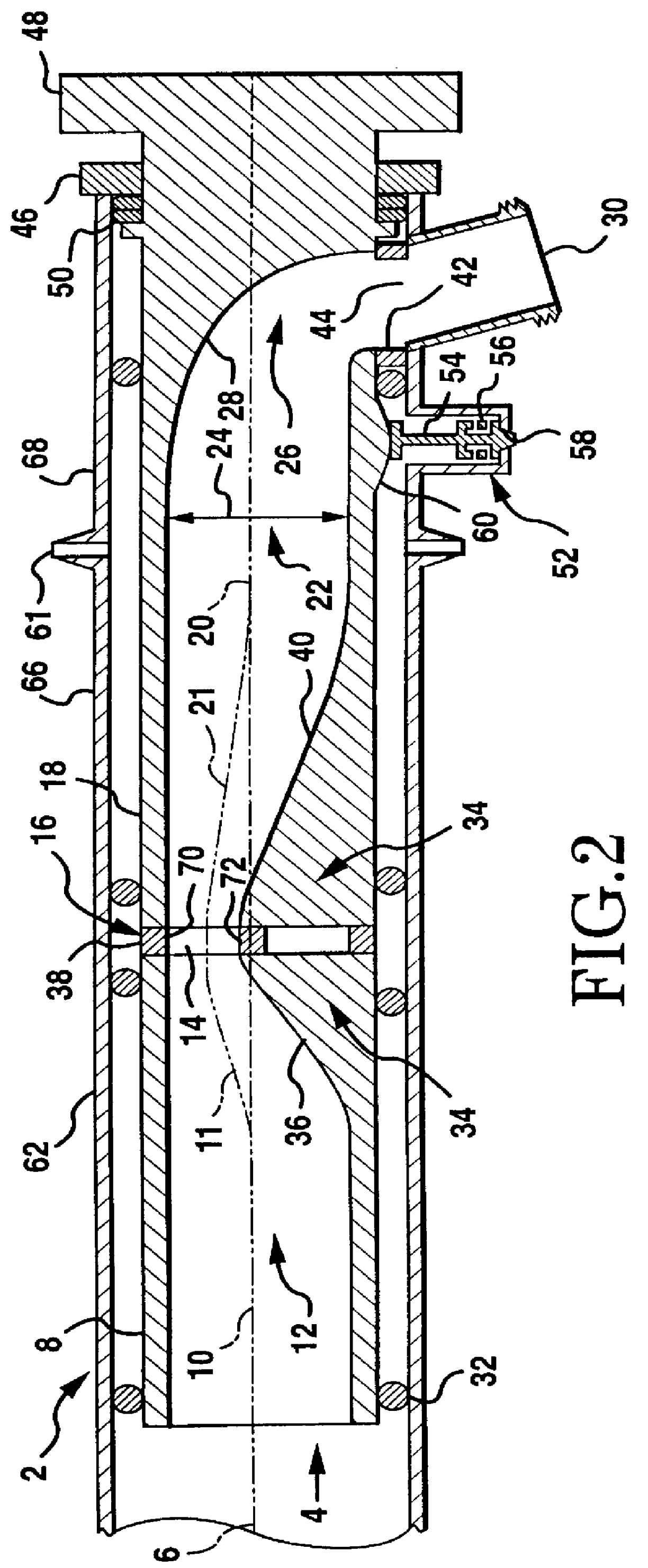
As mentioned earlier, the present invention includes a variety of components that may be used in various combinations, depending on the application that needs to be addressed. This invention is intended to encompass a wide variety of embodiments of an axially-rotated valve. In particular, the invention is designed primarily to take advantage of low friction loss, high efficiency, high flow through an eccentric split venturi of a particular and novel design and combine and modify as needed for a variety of shapes, sizes and orientations, as will be explained in more detail as the figures are described. Elements, functions and procedures that distinguish the present invention will be noted where appropriate.

As can be easily understood, the basic concepts of the present invention may be embodied in a variety of ways. It involves both methods and devices to accomplish the appropriate method. In this patent, the methods are disclosed as part of the results shown to be achieved by the var...


PUM


Abstract

The present invention provides an axially-rotated valve which permits increased flow rates and lower pressure drop (characterized by a lower loss coefficient) by using an axial eccentric split venturi with two portions where at least one portion is rotatable with respect to the other portion. The axially-rotated valve typically may be designed to avoid flow separation and/or cavitation at full flow under a variety of conditions. Similarly, the valve is designed, in some embodiments, to produce streamlined flow within the valve. A typical cross section of the eccentric split venturi may be non-axisymmetric such as a semicircular cross section which may assist in both throttling capabilities and in maximum flow capacity using the design of the present invention. Such a design can include applications for freeze resistant axially-rotated valves and may be fully-opened and fully-closed in one-half of a complete rotation. An internal wide radius elbow typically connected to a rotatable portion of the eccentric venturi may assist in directing flow with lower friction losses. A valve actuator may actuate in an axial manner yet be uniquely located outside of the axial flow path to further reduce friction losses. A seal may be used between the two portions that may include a peripheral and diametrical seal in the same plane.

Description

I. FIELD OF INVENTIONThe present invention relates to an improved flow rate valve system and valve, especially for axially-rotated valves and includes both apparatus and methods. In particular, the present invention has applicability where a freeze resistant valve is preferred.II. BACKGROUND OF THE INVENTIONValves have been used for many centuries in a variety of applications. As the technology has progressed, more sophisticated uses have been found for valves. For instance, various improvements have been made in methods of actuation of the valve. Some of these methods include motor driven actuation, solenoid actuation and more recently, computer controlled actuation, and so forth. However, the essential flow design of valves has stayed relatively constant along four basic designs.One type of valve used is a gate valve. It is simple in design, inexpensive, and can be used in a variety of applications. A gate valve typically contains a circular disk, known as a gate, mounted transver...

Claims


Application Information

Patent Timeline
Patent Type & Authority Patents(United States)
IPC IPC(8): E03B9/02E03B9/00F16K3/02F16K3/08F16K1/22
CPCE03B9/02E03B9/025F16K1/22F16K3/085Y10T137/698Y10T137/0396
Inventor WALRATH, DAVID E.LINDBERG, WILLIAM R.BURGESS, ROBERT K.
Owner BIG HORN VALVE INC
Why Eureka
Try Eureka