Electrical stimulator

A technology of electrical stimulation and electrodes, applied in the fields of electrotherapy, artificial respiration, physical therapy, etc., can solve the problems of unprovided, difficult to know, etc.

Pending Publication Date: 2021-04-16
感性丝绸株式会社
View PDF1 Cites 0 Cited by
  • Summary
  • Abstract
  • Description
  • Claims
  • Application Information

AI Technical Summary

Problems solved by technology

[0007] However, in the device of Patent Document 1, there is a problem that since energy is supplied between the electrode segments A1 and A2 and the electrodes B and C, the electrodes providing stimulation form a multi-electrode-to-multi-electrode relationship, and when a part of the electrodes is in the wiring Insufficient state or contact state between electrodes and the body, it is difficult to know where the defect occurs, and the intended stimulation cannot be provided

Method used


Image

  • Electrical stimulator
  • Electrical stimulator
  • Electrical stimulator

Examples


no. 1 approach

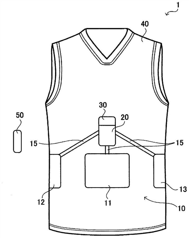
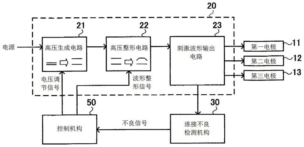
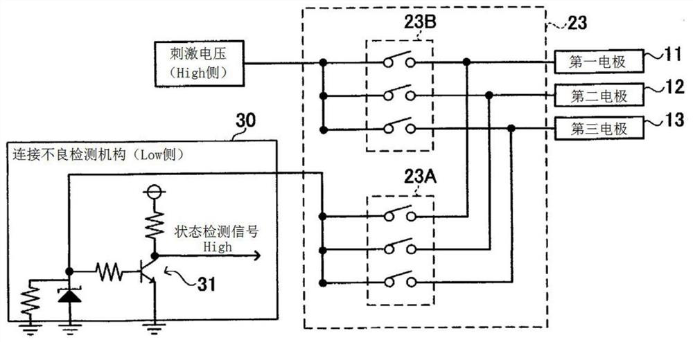
[0044] figure 1 The configuration of the electrical stimulation device 1 according to the first embodiment of the present invention is shown. Figure 2 to Figure 5 The circuit configuration of the electrical stimulation device 1 is shown. The electrical stimulation device 1 provides electrical stimulation to the user, for example, and includes: an electrode group 10 having three or more electrodes, a drive mechanism 20 for supplying energy to the electrode group 10, a poor connection detection mechanism 30 for detecting a poor electrical connection, and a regulation. The clothes 40 of the electrode group 10 and the control mechanism 50 for controlling the driving mechanism 20 are disposed on the position.

[0045]The electrode group 10 is arranged at a predetermined position in contact with the user's body, for example. In this embodiment, for example, the electrode group 10 is arranged on the torso such as the abdomen, and has at least three electrodes. Specifically, it in...

no. 2 approach

[0076] Figure 9 It is a drawing which shows the structure of the electrical stimulation apparatus 2 which concerns on 2nd Embodiment of this invention. Figure 10 It is a drawing explaining the operation of the electrical stimulation device 2 . This electrical stimulation device 2 has the same configuration as that of the first embodiment except that the configurations of the electrode group 210 and the drive mechanism 220 are different. Therefore, the same reference numerals are assigned to the same components as those in the first embodiment, and the corresponding components are given reference numerals with 200 added, and detailed description of the same parts will be omitted.

[0077] Like the first embodiment, the electrode group 210 is arranged on the torso such as the abdomen, and has at least four electrodes. Specifically, there are: a first electrode 211 corresponding to the right rectus abdominis, a second electrode 212 corresponding to the left rectus abdominis, ...

no. 3 approach

[0083] Figure 11 It is a drawing which shows the structure of the electrical stimulation apparatus 3 which concerns on 3rd Embodiment of this invention. Figure 12 to Figure 15 It is a drawing showing the circuit configuration of the electrical stimulation device 3 . The electrical stimulation device 3, for example, provides electrical stimulation to the user, and includes: an electrode group 310 having three or more electrodes, a drive mechanism 320 for supplying energy to the electrode group 310, a poor connection detection mechanism 330 for detecting a poor electrical connection, and a regulation. The clothing 340 with the electrode group 310 and the control mechanism 350 that controls the driving mechanism 320 are arranged on the position.

[0084] The electrode group 310 is arranged at a predetermined position in contact with the user's body, for example. In this embodiment, for example, the electrode group 310 is arranged on the torso such as the abdomen, and has at l...


PUM


Abstract

To provide an electrical stimulator that allows defective electrical connections to be detected readily. This electrical stimulator 1 comprises an electrode group 10 comprising three or more electrodes, and a drive means 20 for energizing the electrode group 10. The drive means 20 is constituted in such a manner as to assign a first polarity to one electrode among the electrode group 10 and a second polarity to the remaining plurality of electrodes, and to energize the electrode group 10 by sequentially switching the electrode having the first polarity. In addition, this electrical stimulator 1 comprises a defective connection detection means 30 that detects a defect in the electrical connection by detecting whether or not electrical stimuli have been applied to the user when the electrode group 10 has been energized.

Description

technical field [0001] The present invention relates to an electrical stimulation device for providing electrical stimulation to a body using an electrode set having more than three electrodes. Background technique [0002] In recent years, electrical stimulation devices have been known that provide electrical stimulation to the body by contacting electrodes to predetermined positions of the body to perform muscle training and the like. Such electrical stimulation devices include, for example, devices that supply energy to specific pairs of electrodes and provide electrical stimulation between these electrodes. For example, a device is described in Patent Document 1, which is provided with electrode segments A1 and A2 adapted to the lower waist of the patient's body, and electrodes B and C respectively adapted to the flanks on the opposite side of the patient's body, and alternately provided on the electrode segments A1 and A2. A first set of muscle stimulating current puls...

Claims


Application Information

Patent Timeline
Patent Type & Authority Applications(China)
IPC IPC(8): A61N1/36
CPCA61N1/0476A61N1/0484A61N2001/083A61N1/36
Inventor 冈野秀生目黑伸哉
Owner 感性丝绸株式会社
Why Eureka
Try Eureka