Check patentability & draft patents in minutes with Patsnap Eureka AI!

A bridge steel strand stress relief device and its working method

A technology for stress relief, bridge steel, applied in the field of steel strands

Active Publication Date: 2022-04-19
AOSHENG MAANSHAN STEEL WIRE & WIRE ROPE
View PDF7 Cites 0 Cited by
  • Summary
  • Abstract
  • Description
  • Claims
  • Application Information

AI Technical Summary

Problems solved by technology

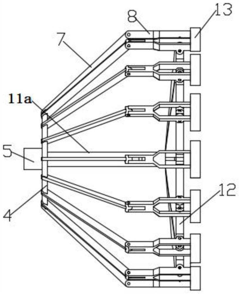
[0004] The object of the present invention is to provide a steel strand stress relief device for bridges and its working method, which solves the following technical problems: (1) by inserting a plurality of steel strands into a plurality of wire entry holes one by one, the steel strands After passing through the wire hole and through the steel strand sleeve, open the installation cylinder, the piston rod of the installation cylinder shrinks and drives the guide rod to move horizontally, the guide rod slides along the guide sleeve, and the guide rod drives the second annular plate to move horizontally and then rotate The seat and the rotating arm cooperate to rotate, the rotating seat drives the steel strand sleeve to rotate, and the steel strand sleeve drives the steel strand to rotate. Through the above structure, the steel strand stress relief device for the bridge can gather multiple strands of steel strand into one Strands, and then the stress relief work can be performed on multiple strands of steel strands at the same time to ensure that the stress relief of multiple strands of steel strands is carried out simultaneously; The last steel strands pass through the rotating cylinder, and the three guide cylinders in the rotating cylinder are opened. The piston rod of the guiding cylinder pushes the guide block, and the guide block slides along the guide rod two and drives the two second rotating rods to rotate. The rotating rod cooperates with the four first rotating rods to drive the limit bar to move in the rotating cylinder. The three limit bars in the rotating cylinder move towards each other. The output shaft drives the gear to rotate, and the gear cooperates with the gear ring to drive the rotating cylinder to rotate. The rotating cylinder drives three limit bars to rotate, and the three limit bars drive the gathered steel strands to rotate. Through the above structure, the bridge uses steel strands The wire stress relief device can limit the gathered steel strands to prevent the situation that the steel strands cannot be gathered due to their own stress before the stress is relieved. The three limit bars can meet the limit of steel strands with different diameters. At the same time, the steel strands are driven to rotate by three limit bars after the limit, and several steel strands are twisted into bundles to prevent the individual steel strands from retracting under the influence of stress, and to facilitate the subsequent stress relief work; (3) The gathered steel strand first passes between the two stress relief rollers near the side of the 
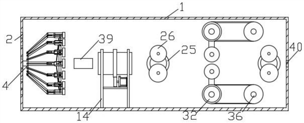
rotating drum, then passes between the two limit rollers, and finally passes through the two stress relief rollers near the outlet hole. Roller, turn on the two installation motors, the output shaft of the installation motor drives the center gear to rotate, the center gear meshes to drive the two planetary gears to rotate, the two planetary gears drive the two roller bars to rotate, the two roller bars drive the two stress relief rollers to rotate, The two stress relief rollers drive the gathered steel strand to rotate, and the limit motor is turned on, the output shaft of the limit motor drives one of the pulleys to rotate three times, the two pulleys three drive the belt two to rotate, the three pulleys drive the axis rod to rotate, the axis The rod drives the second pulley to rotate, the second pulley drives the first pulley to rotate through the first belt, the first pulley drives the epicyclic roller to rotate, the epicyclic roller drives the two right-angled connecting blocks to rotate, the right-angled connecting block drives the connecting arm to rotate, and the two connecting arms drive the limit roller cycle The two limit rollers pull the gathered steel strands up and down periodically, and the steel strands are conveyed out from the outlet hole after the stress is relieved. Through the setting of two sets of rotatable stress relief rollers, the steel strands can be adjusted Repeated guidance in different directions, combined with two limit rollers that can be raised and lowered periodically, can bring The moving steel strand is repeatedly raised and lowered to effectively eliminate the stress of the steel strand

Method used


Image

  • A bridge steel strand stress relief device and its working method
  • A bridge steel strand stress relief device and its working method
  • A bridge steel strand stress relief device and its working method

Examples


Embodiment Construction

[0037] The following will clearly and completely describe the technical solutions in the embodiments of the present invention with reference to the accompanying drawings in the embodiments of the present invention. Obviously, the described embodiments are only some, not all, embodiments of the present invention. Based on the embodiments of the present invention, all other embodiments obtained by persons of ordinary skill in the art without creative efforts fall within the protection scope of the present invention.

[0038] see Figure 1-12 As shown, the present invention is a stress relief device for steel strands for bridges, comprising a stress relief chamber 1, a number of wire inlet holes 2 are provided on one side of the stress relief chamber 1, and an installation cylinder 3 is installed on one side of the stress relief chamber 1. The inner wall of the elimination chamber 1 is equipped with a guide sleeve 5, the first annular plate 4 is installed on the guide sleeve 5, a...


PUM


Abstract

The invention discloses a steel strand stress relief device for bridges and a working method thereof. It comprises a stress relief chamber. A number of wire inlet holes are opened on one side of the stress relief chamber. An installation cylinder is installed on one side of the stress relief chamber. There is a guide sleeve, the first annular plate is installed on the guide sleeve, a number of rotating arms are installed on the first annular plate, a number of rotating seats are installed on the rotating arm, steel strand sleeves are installed on the rotating seat, and a number of steel strands The sleeve corresponds to a plurality of wire entry holes one by one. The present invention can gather multiple strands of steel strands into one strand, and then perform stress relief work on multiple strands of steel strands at the same time, ensuring that the stress relief of multiple strands of steel strands is carried out synchronously. The limit of the stranded wire, after the limit at the same time, the steel strand is driven to rotate through three limit bars, and several steel strands are twisted into bundles to prevent the individual steel strands from retracting under the influence of stress, which is convenient for follow-up Perform stress relief work.

Description

technical field [0001] The invention relates to the technical field of steel strands, in particular to a steel strand stress relief device for bridges and a working method thereof. Background technique [0002] Most of the steel wires used in the production of steel strands are cold-drawn high-carbon steel wires. The steel wires used are produced by the coils after descaling, coating, drying, and drawing. The coils are elongated and thinned to produce steel wires. During the process, tensile stress will be generated on the surface of the steel wire, and compressive stress will be generated inside. Due to the existence of these stresses, the produced steel wire will be rewound and twisted, which makes the construction inconvenient. [0003] The patent document (201922150715.6) discloses a stress relief device for steel strands. The stress relief device pulls the uncoiled steel strands to the stress relief wheels on the stress relief floor through traction wheels. The strand...

Claims


Application Information

Patent Timeline
Patent Type & Authority Patents(China)
IPC IPC(8): C21D10/00
Inventor 汤亮倪晓峰李红明王钧郑龙军
Owner AOSHENG MAANSHAN STEEL WIRE & WIRE ROPE
Features
  • R&D
  • Intellectual Property
  • Life Sciences
  • Materials
  • Tech Scout
  • Unparalleled Data Quality
  • Higher Quality Content
  • 60% Fewer Hallucinations
Learn More