
Extremely-low-frequency air bag vibration isolation system

A vibration isolation system and extremely low frequency technology, which is applied in the direction of vibration suppression adjustment, spring/shock absorber, mechanical equipment, etc., can solve the problem of unsatisfactory vibration isolation effect, failure to better meet vibration isolation needs, short circuit of lateral elastic body, etc. question

Active Publication Date: 2021-04-20
NAVAL UNIV OF ENG PLA
View PDF7 Cites 3 Cited by
  • Summary
  • Abstract
  • Description
  • Claims
  • Application Information

AI Technical Summary

Problems solved by technology

"Smart Airbag Vibration Isolation Device" (Patent No. 200910063656.7) is a vibration isolation device built with smart airbag technology, which can better isolate mechanical vibration and has the function of automatic inflation and deflation. Vibration isolation is not ideal
"A Negative Stiffness Adjustable Zero Stiffness Vibration Isolation Device" (Patent No. 201921442791.8) uses an adjustable negative stiffness mechanism to enable the device to be in an ideal state with dynamic stiffness close to zero under static load, avoiding the failure of the vibration isolation system , but the load capacity of the device is limited, and it cannot meet the vibration isolation requirements under large loads and small displacements, and the lateral elastic body is horizontally limited. When used as a device, the lateral elastic body may be short-circuited. Causes the vibration to be transmitted from the limit device

Method used


Image

  • Extremely-low-frequency air bag vibration isolation system
  • Extremely-low-frequency air bag vibration isolation system
  • Extremely-low-frequency air bag vibration isolation system

Examples


Embodiment Construction

[0028] The principles and features of the present invention are described below in conjunction with the accompanying drawings, and the examples given are only used to explain the present invention, and are not intended to limit the scope of the present invention.

[0029] In the description of the present invention, it should be understood that the orientation or positional relationship indicated by the terms "vertical", "lateral", "upper", "lower", "vertical", "horizontal" etc. are based on the drawings The orientations or positional relationships shown are only for the convenience of describing the present invention and simplifying the description, and do not indicate or imply that the referred device or element must have a specific orientation, be constructed and operated in a specific orientation, and therefore cannot be construed as an important aspect of the present invention. limits. In addition, the terms "a" and "two" are used for descriptive purposes only, and cannot...


PUM


Abstract

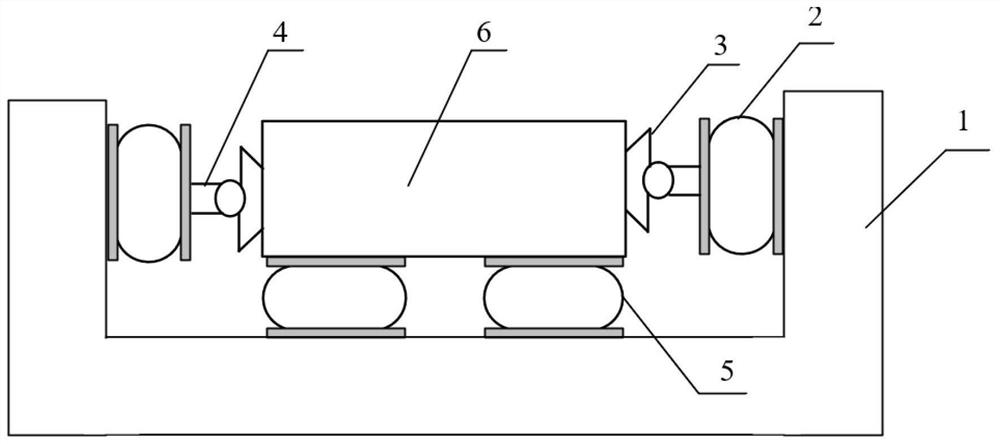
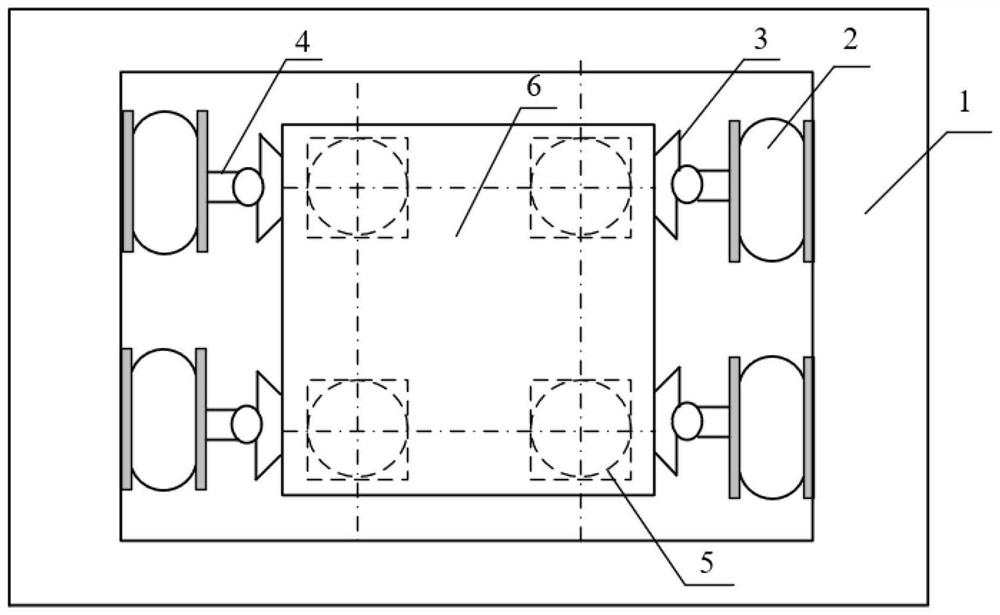
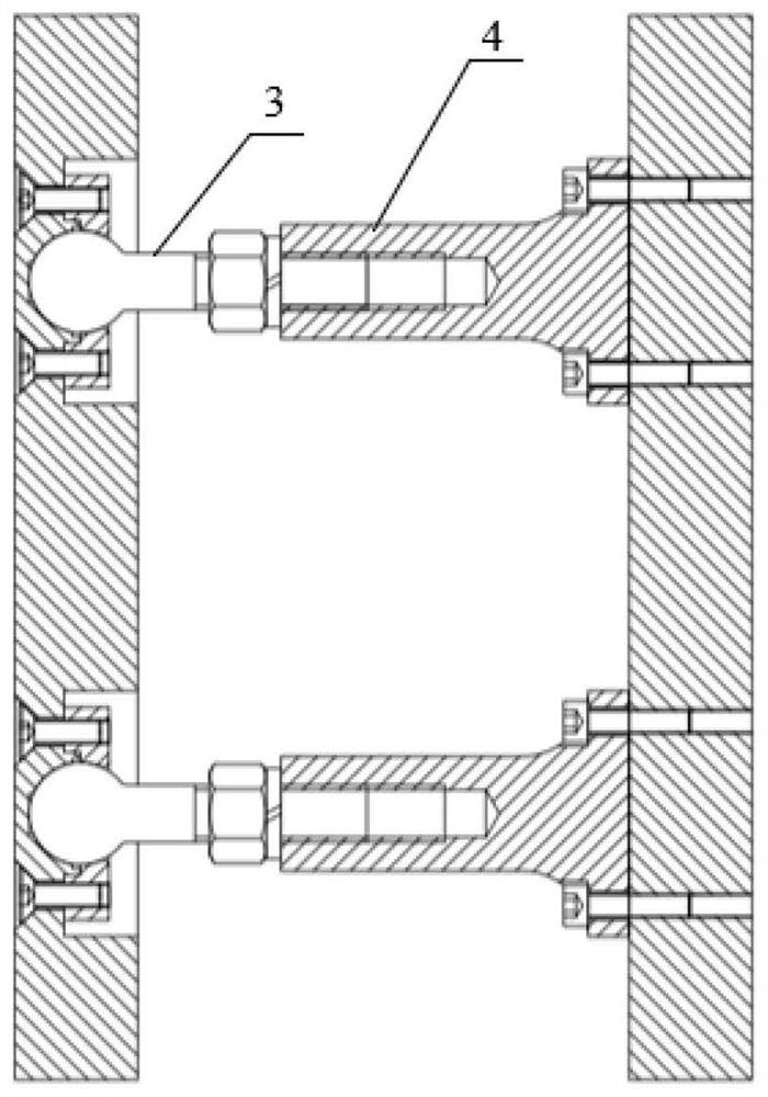
The invention relates to an extremely-low-frequency air bag vibration isolation system. The extremely-low-frequency air bag vibration isolation system mainly comprises a vertical air bag vibration isolator, a lateral air bag vibration isolator, a rotating structure, a connecting structure and a loading platform; the vertical air bag vibration isolator is used for bearing loads and achieving vertical vibration isolation; the lateral air bag vibration isolators are used for improving the stability of the system, preventing the loading platform from directly colliding with a lateral foundation under the working conditions of swinging and the like, and meanwhile achieving lateral vibration isolation; the rotating structure and the connecting structure are used for reducing the adverse effect of the lateral air bag vibration isolator on the system and ensuring the system stability under the working conditions of swinging and the like; and meanwhile, on the basis of the structure, the rotation rigidity of the lateral air bag vibration isolator can be reduced through the design of the lateral air bag vibration isolator, negative rigidity is provided for the system, and the vibration isolation performance is further improved. The vibration isolation system is simple in structure, high in reliability and low in cost, and can be used for low-frequency efficient vibration isolation of mechanical equipment and systems for industry and civil use, especially in the field of ships and warships.

Description

technical field [0001] The invention relates to the technical field of vibration reduction and noise reduction processing, in particular to an extremely low frequency airbag vibration isolation system. Background technique [0002] Controlling the vibration caused by mechanical equipment to meet the standard requirements is the key to the design of industrial, civil, and especially marine machinery systems, and the control of low-frequency vibration is particularly important. Using a vibration isolation system is one of the most effective ways to reduce the vibration transmission of equipment. The airbag vibration isolation system generally consists of a vertical airbag vibration isolator, a lateral airbag vibration isolator, and a loading platform. The vertical airbag vibration isolator supports the load and realizes vertical vibration isolation. The purpose of introducing the lateral airbag vibration isolator is to improve the stability of the system in swaying and other...

Claims


Application Information

Patent Timeline
IPC IPC(8): F16F15/023
Inventor 帅长庚李步云杨兆豪何琳
Owner NAVAL UNIV OF ENG PLA
Learn More