
Down lamp structure and dismounting method thereof

A technology of downlights and cylinders, applied in lighting devices, lighting auxiliary devices, fixed lighting devices, etc., can solve problems such as gaps, affecting the integrity of the appearance of the ceiling, and damage to the wall of the installation hole

Active Publication Date: 2021-04-20
上海艾特照明设计有限公司
View PDF16 Cites 0 Cited by
  • Summary
  • Abstract
  • Description
  • Claims
  • Application Information

AI Technical Summary

Problems solved by technology

[0004] However, when disassembling the downlight, the downlight needs to be removed from the ceiling. Since the spring clip on the downlight abuts against the upper surface of the ceiling, the spring clip will be forced to fold away from the face ring of the downlight. The torsion spring of the spring clip continues to be stressed. During the process of removing the downlight, the spring clip of the downlight will continue to abut against the wall of the installation hole and continue to exert force on the wall of the hole, so it is easy to cause the installation hole in the ceiling to be damaged. The wall breaks, creating a gap that both affects the cosmetic integrity of the ceiling and causes operator discomfort due to falling debris from the hole wall

Method used


Image

  • Down lamp structure and dismounting method thereof
  • Down lamp structure and dismounting method thereof
  • Down lamp structure and dismounting method thereof

Examples


Embodiment Construction

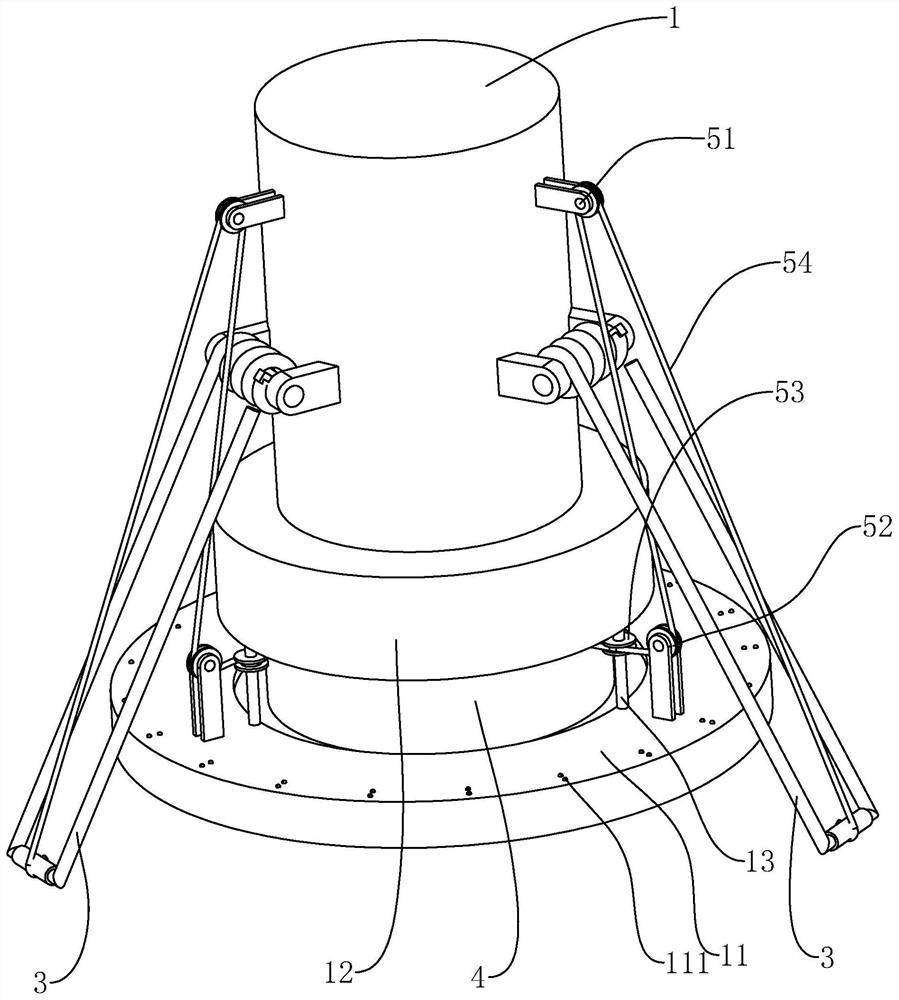
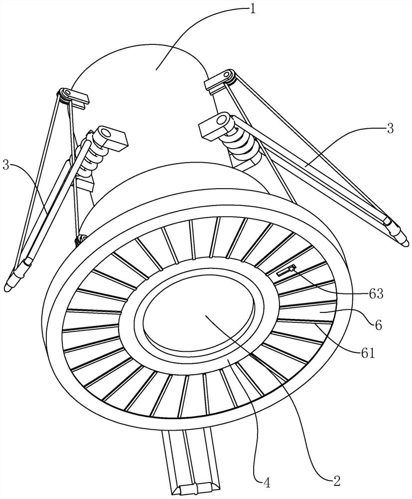
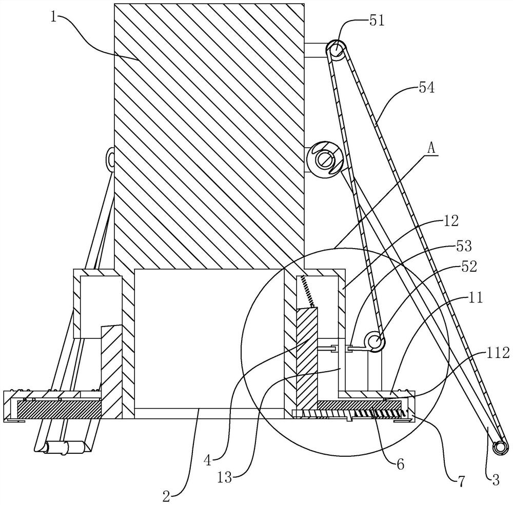
[0037] The following is attached Figure 1-5 The application is described in further detail.

[0038] The embodiment of the application discloses a downlight structure. refer to figure 1 , including a cylinder 1 and a lamp body 2 arranged in the cylinder 1, a sheet-shaped abutment ring 11 is fixed on the outer peripheral wall of the lower end of the cylinder 1, and three spring clips evenly arranged around the circumference are provided on the outer peripheral wall of the cylinder 1 3. When the torsion spring of the spring clip 3 is under no force, the free end of the spring clip 3 is set inclined downward; when it is fixed normally, the cylinder 1 is located in the installation hole of the ceiling, and the abutment ring 11 on the cylinder 1 is on the The surface abuts against the lower surface of the ceiling, while the free end of the spring clip 3 on the cylinder body 1 presses downward against the upper surface of the ceiling. The combination of the two abutting forces co...


PUM


Abstract

The invention relates to a down lamp structure and a dismounting method thereof. The down lamp structure comprises a barrel body and a lamp body arranged in the barrel body, a plurality of spring clamps are arranged on the outer circumferential face of the barrel body, the outer circumferential face of the barrel body is rotationally sleeved with a winding barrel, traction ropes are arranged at the free ends of the spring clamps, and the other ends of the traction ropes bypass guide pieces arranged on the barrel body. The ends of the traction ropes and the winding barrel are fixedly arranged; and one end of the barrel body is rotationally connected with a control ring for controlling the winding barrel to rotate. By rotating the control ring exposed out of the ceiling, the spring clamps abutting against the interior of the ceiling can be controlled to be turned over upwards, so that the situation that when the down lamp is taken down, due to the large exposed size of the spring clamps, the hole wall of the mounting hole of the ceiling is interfered and damaged is reduced, and therefore the appearance integrity of the ceiling is guaranteed; meanwhile, subsequent installation of the down lamp is also facilitated, and convenience and quickness are achieved.

Description

technical field [0001] The present application relates to the field of lamp structures, in particular to a downlight structure and a disassembly method thereof. Background technique [0002] With the continuous advancement of science and technology, various lamps are widely used in daily life. Downlights are used as decorative lamps on the ceiling to realize the function of indoor lighting. [0003] The general downlight is provided with two spring clips arranged opposite to each other, and the face ring of the downlight is pressed against the outer end surface of the ceiling by the elastic force of the spring clips, that is, the downlight is installed in the installation hole of the ceiling. [0004] However, when disassembling the downlight, the downlight needs to be removed from the ceiling. Since the spring clip on the downlight abuts against the upper surface of the ceiling, the spring clip will be forced to fold away from the face ring of the downlight. The torsion sp...

Claims


Application Information

Patent Timeline
IPC IPC(8): F21S8/04F21V21/03F21V17/16
Inventor 张先军
Owner 上海艾特照明设计有限公司
Learn More